Collaborative virtual network mapping method

A technology of virtual network mapping and virtual network, which is applied in the field of virtual network mapping to achieve the effects of load reduction, system single point failure problem mitigation, and scalability problem mitigation

Inactive Publication Date: 2016-09-14
BEIJING UNIV OF POSTS & TELECOMM
View PDF4 Cites 15 Cited by
  • Summary
  • Abstract
  • Description
  • Claims
  • Application Information

AI Technical Summary

Problems solved by technology

[0007] Therefore, traditional centralized and distributed mapping algorithms have their own advantages and disadvantages

Method used


Image

  • Collaborative virtual network mapping method
  • Collaborative virtual network mapping method
  • Collaborative virtual network mapping method

Examples


Embodiment Construction

[0027] In order to make the object, technical solution and advantages of the present invention clearer, the present invention will be further described in detail below in conjunction with the accompanying drawings.

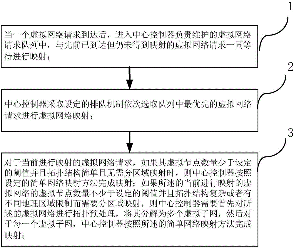
[0028] see figure 1 , introducing a collaborative virtual network mapping method proposed by the present invention, said method comprising the following steps:

[0029] (1) When a virtual network request arrives, it enters the virtual network request queue maintained by the central controller, and waits for mapping together with the previously arrived but unmapped virtual network request;

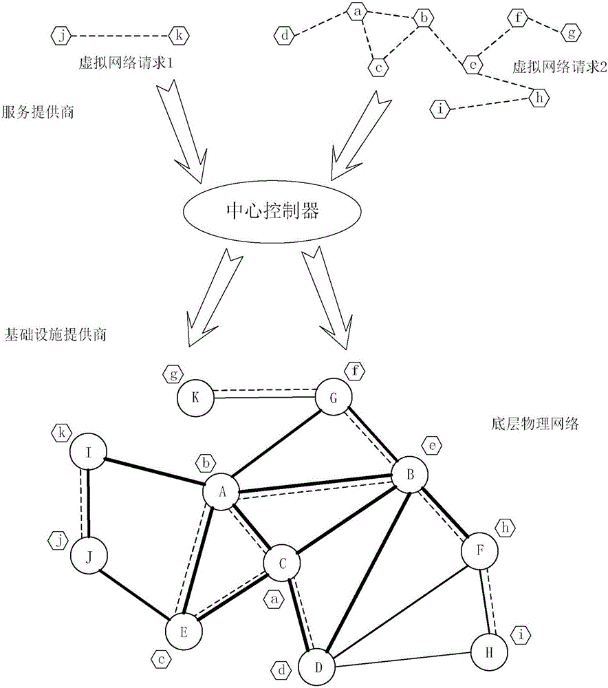
[0030] see figure 2 , figure 2 The lower part shows the underlying physical network of the infrastructure provider, including 11 underlying physical nodes indicated by circles and 17 underlying physical links indicated by solid lines. The 11 underlying physical nodes are sequentially numbered as capital letters A, B, C, D, E, F, G, H, I, J, and K. figure 2 The upper part...


PUM


Abstract

The invention provides a collaborative virtual network mapping method, comprising the following steps: (1) when a virtual network request arrives, entering a central controller to wait for mapping; (2) selecting an virtual network request with the top priority in a queue by the central controller to carry out mapping; (3) for the virtual network request, if the number of virtual nodes thereof is smaller than a set threshold, a topological structure is simple, and no subregional mapping is needed, accomplishing mapping according to a simple network mapping method; and otherwise, carrying out topology preprocessing on the virtual network request by the central controller to decompose the same into a plurality of virtual sub-networks, and mapping each virtual sub-network according to the simple network mapping method by the central controller. According to the method provided by the invention, relative advantages of a centralized algorithm and a distributed algorithm are fully integrated to achieve better mapping performance.

Description

technical field [0001] The invention relates to a method for realizing virtual network mapping, which belongs to the technical field of computer networks, in particular to the technical field of network virtualization. Background technique [0002] Network virtualization refers to the logical abstraction of a shared underlying physical network as an infrastructure into virtual resource slices through virtualization technology, and then divides it into multiple isolated, heterogeneous virtual networks with their own specific topological structures. . In the network virtualization environment, traditional network service providers are naturally differentiated into infrastructure providers responsible for deploying, managing and maintaining underlying physical network resources, and renting virtual resources provided by infrastructure providers to build virtual networks to provide end users with diverse Service providers of customized services. Service providers can make full...

Claims


Application Information

Patent Timeline
IPC IPC(8): H04L12/46
CPCH04L12/4641H04L12/4675
Inventor 廖建新张磊丰旻卿苏德王晶张成
Owner BEIJING UNIV OF POSTS & TELECOMM
Why Eureka
Try Eureka