Non-surgical treatment system for cervical decompression

A decompression treatment and cervical spine technology, applied in the field of non-surgical cervical spine decompression treatment systems, can solve the problems of limited treatment effect, and achieve the effects of simple structure, good plasticity and good elasticity

Active Publication Date: 2016-09-21
ZHENGZHOU FEILONG MEDICAL EQUIP CO LTD
View PDF7 Cites 2 Cited by
  • Summary
  • Abstract
  • Description
  • Claims
  • Application Information

AI Technical Summary

Problems solved by technology

The cervical spine decompression methods commonly used in clinical practice are mostly a combination of the above methods. Usually, continuous vertical decompression in the sitting position is used, and simple stretching along the direction

Method used


Image

  • Non-surgical treatment system for cervical decompression
  • Non-surgical treatment system for cervical decompression
  • Non-surgical treatment system for cervical decompression

Examples


Embodiment Construction

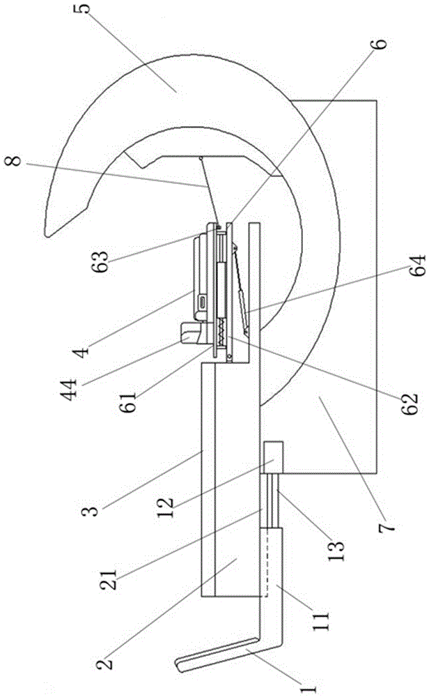
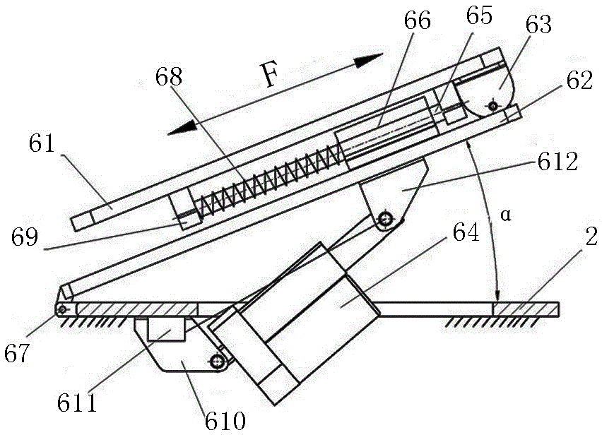
[0025] Such as Figure 1-8As shown, the non-surgical cervical spine decompression treatment system includes a decompression bed 2, a decompression control cabinet 5 and a decompression sliding assembly 6. The end touches the bottom, and the pulling adjustment device 6 includes a headrest bottom plate 61 and a fixed plate 62. One end of the headrest bottom plate 61 is equipped with a decompression assembly 63, and the decompression assembly 63 is connected with the decompression control cabinet 5 through a decompression belt 8. The base plate 61 is movably connected with the fixed plate 62. A guide rod 65 is installed on the head pad base plate 61. The guide rod 65 is sleeved with a linear bearing. The linear bearing is installed on the fixed plate 62 through a bearing seat 66. The sliding resistance is small and the structure is simpler. The two ends of the guide rod 65 are fixed on the head pad bottom plate 61 through the support seat 69, and a return spring 68 is arranged be...


PUM


Abstract

The invention relates to the field of medical devices, in particular to a non-surgical treatment system for cervical decompression.The non-surgical treatment system comprises a pressure decompression bed, a pressure decompression control cabinet and a pressure decompression sliding assembly. The middle part of the pressure decompression bed is hinged onto a bed frame and can overturn to the bottom end of the pressure decompression bed. The pressure decompression sliding assembly comprises a headrest bottom plate and a fixing plate. One end of the headrest bottom plate is provided with a pressure decompression assembly. The pressure decompression assembly is connected with the pressure decompression control cabinet through a pressure decompression belt. The headrest bottom plate is movably connected with the fixing plate. One end of the fixing plate is hinged onto the front end of the decompression bed. A headrest is fixed on the headrest bottom plate. The upper surface of the headrest is provided with a groove matching the shape of an afterbrain of a human body. One side of the neck of the headrest is provided with two separable and fixed astoid bone rubber support blocks which are correspondingly fixed below the two mastoid bones. The two mastoid bone support blocks draw close to the part of the inner side and are in the conical shapes. The vertex of a taper points to the mastoid bone part of each headrest and the vertex of a taper is a fillet.

Description

technical field [0001] The invention relates to the field of medical equipment, in particular to a non-operative cervical decompression treatment system. Background technique [0002] Cervical spondylosis is a common and frequently-occurring disease, which refers to cervical bone hyperplasia caused by cervical intervertebral disc degeneration, cervical hypertrophy and cervical injury, or intervertebral disc prolapse, ligament thickening, stimulation or compression of cervical spinal cord, cervical nerves, A clinical syndrome that produces a series of symptoms due to blood vessels. With the continuous acceleration of people's pace of life, the incidence of cervical spondylosis is increasing year by year. After the disease occurs, patients often suffer from symptoms such as cervical spine pain, neck, shoulder and arm pain, and numbness of limbs, which brings a lot of inconvenience to patients' daily life. Currently, there are two types of treatments for cervical spondylosis: ...

Claims


Application Information

Patent Timeline
IPC IPC(8): A61F5/042A61F5/045A61H1/02A61M16/06
CPCA61F5/042A61H1/0222A61H1/0296A61H2201/0142A61H2205/04A61M16/06
Inventor 张新民李洪涛
Owner ZHENGZHOU FEILONG MEDICAL EQUIP CO LTD
Why Eureka
Try Eureka