Fixing punching mechanism for plastic cylinder

A cylinder and plastic technology, applied in metal processing and other directions, can solve the problems of no specific clamping device, affecting cutting effect, cylinder deformation, etc., and achieve the effect of convenient disassembly and replacement, good effect and high efficiency

Active Publication Date: 2016-09-21
佛山市顺德区壹爽美塑胶制品有限公司
View PDF7 Cites 20 Cited by
  • Summary
  • Abstract
  • Description
  • Claims
  • Application Information

AI Technical Summary

Problems solved by technology

[0002] When the existing cylindrical plastic products need to groove or dig holes in their side walls, they need to use equipment to clamp the cylinder body, but now there is no specific clamping device, which generally uses two screw screws Connected to the support plate, through the rotation of two screws, the clamp blocks fixed at the ends of the two screws clamp and fix the cylinder body, and then manually punch holes, which is very troublesome, and when punching holes, due to the circular The inside of the cylinder is hollow, and its cutting will easily deform the cylinder and affect the cutting effect

Method used


Image

  • Fixing punching mechanism for plastic cylinder
  • Fixing punching mechanism for plastic cylinder
  • Fixing punching mechanism for plastic cylinder

Examples


Embodiment

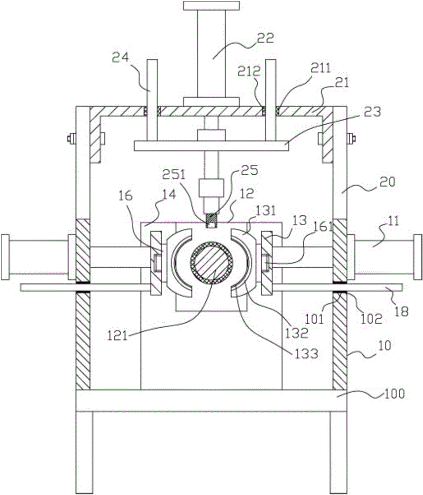
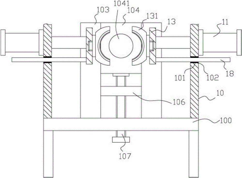
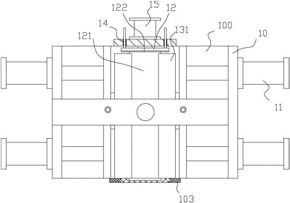
[0020] Example: see Figure 1 to Figure 4 As shown, a fixed punching mechanism for a plastic cylinder includes a frame 100, an upper support plate 10 is fixed on the left and right sides of the top plate of the frame 100, and at least Two clamping cylinders 11, the push rods of the two clamping cylinders 11 pass through the upper support plate 10, the ends of the push rods clamping the cylinders 11 are fixed with connecting plates 13, and the opposite surfaces of the two connecting plates 13 are fixed There are arc-shaped clamping blocks 131, and the arc-shaped inner walls of the two arc-shaped clamping blocks 131 are corresponding. The middle part of the top surface of the two upper support plates 10 is fixed with a vertical support plate 20, and the two ends of the punching cylinder connecting frame 21 are fixed. On the inner side walls of the upper part of the two vertical support plates 20, the stamping cylinder 22 is fixed on the top surface of the middle part of the top ...


PUM


Abstract

The invention discloses a fixing punching mechanism for a plastic cylinder. The fixing punching mechanism comprises a rack. Upper supporting plates are fixed to the top surfaces of the left side and the right side of a top plate of the rack. At least two clamping air cylinders are fixed to the outer side walls of the upper supporting plates. Pushing rods of the two clamping air cylinders penetrate through the upper supporting plates. Connecting plates are fixed to the ends of the pushing rods of the clamping air cylinders. Arc-shaped clamping blocks are fixed to the opposite surfaces of the two connecting plates. Vertical supporting plates are fixed to the middles of the top surfaces of the two upper supporting plates. The two ends of a stamping air cylinder connecting frame are fixed to the upper inner side walls of the two vertical supporting plates. A stamping air cylinder is fixed to the top surface of the middle of a top plate of the stamping air cylinder connecting frame. A pushing rod of the stamping air cylinder vertically and downwards penetrates through the top plate of the stamping air cylinder connecting frame. A guiding connecting plate is fixed to the pushing rod of the stamping air cylinder. According to the fixing punching mechanism for the plastic cylinder, automatic clamping is conducted by adopting the clamping air cylinders, a cylinder block is inserted in the cylinder in a sleeved mode, and punching is automatically conducted; the fixing punching mechanism is high in efficiency and good in effect; and the effect that the cylinder is deformed due to punching is avoided is ensured through the cylinder block.

Description

Technical field: [0001] The invention relates to the technical field of plastic processing equipment, in particular to a fixed punching mechanism for a plastic cylinder. Background technique: [0002] When the existing cylindrical plastic products need to groove or dig holes in their side walls, they need to use equipment to clamp the cylinder body, but now there is no specific clamping device, which generally uses two screw screws Connected to the support plate, through the rotation of two screws, the clamp blocks fixed at the ends of the two screws clamp and fix the cylinder body, and then manually punch holes, which is very troublesome, and when punching holes, due to the circular The inside of the cylinder is hollow, and its cutting will easily deform the cylinder and affect the cutting effect. Invention content: [0003] The object of the present invention is to address the deficiencies of the prior art, and to provide a plastic cylinder fixed punching mechanism, whi...

Claims


Application Information

Patent Timeline
Patent Type & Authority Applications(China)
IPC IPC(8): B26F1/14B26D7/02
CPCB26D7/02B26D2007/013B26F1/0015B26F1/14
Inventor 付淑珍
Owner 佛山市顺德区壹爽美塑胶制品有限公司
Why Eureka
Try Eureka