
Dump Truck Screw Lifting System

A technology of dump trucks and lead screws, which is applied to the arrangement of loading and unloading vehicles, motor vehicles, and vehicles used for freight transportation. It can solve the problems of high risk and complicated production of hydraulic lifting systems, and avoid uneven distribution of shaft cores. , Guarantee the effect of safety and convenient processing

Active Publication Date: 2018-03-09
李岳
View PDF6 Cites 0 Cited by
  • Summary
  • Abstract
  • Description
  • Claims
  • Application Information

AI Technical Summary

Problems solved by technology

[0004] The purpose of the present invention is to provide a screw lifting system for dump trucks, which has solved the problems of high risk and complicated production in the process of using the existing hydraulic lifting system

Method used


Image

  • Dump Truck Screw Lifting System
  • Dump Truck Screw Lifting System
  • Dump Truck Screw Lifting System

Examples


Embodiment Construction

[0018] This lifting system is mainly used for light-weight front roof and 6*4 light-duty dump vehicles. The lifting system is composed of a hydraulic system assembly and a power transmission assembly.

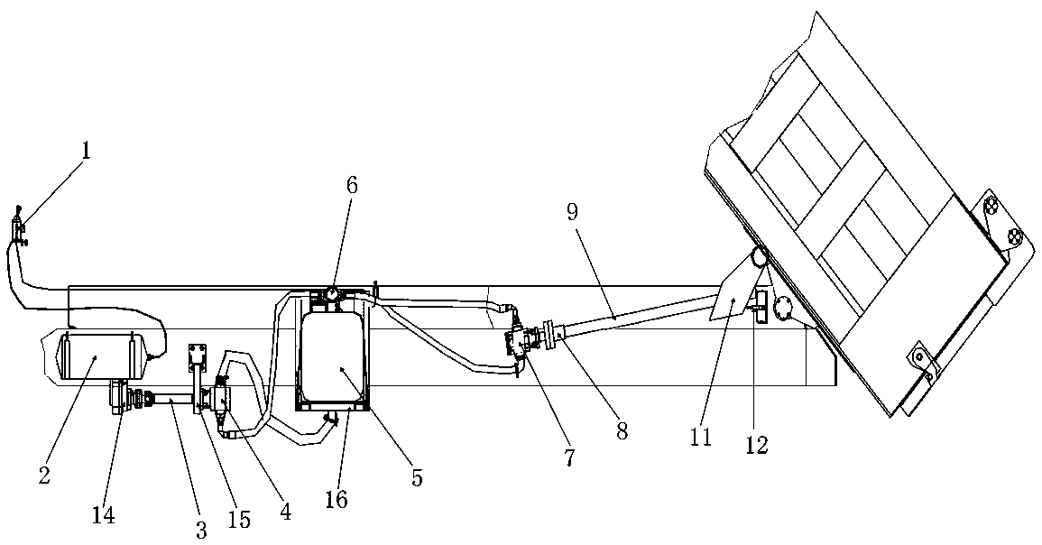
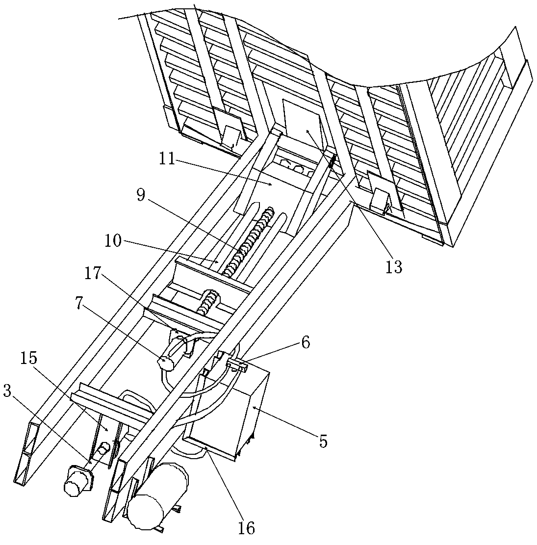
[0019] Such as figure 1 , figure 2 As shown, the hydraulic system assembly is composed of a control valve 1, an air tank 2, an oil pump 4, a transmission shaft 3, a chassis power take-off 14, a fuel tank 5, a three-position four-way distribution valve 6 and a limit valve 12. The control valve 1 (two-position three-way directional control valve, normally open type) is arranged in the cab, the gas tank 2 is the gas tank that comes with the chassis of the car, and is arranged on the chassis beam, and the air inlet of the control valve 1 passes through the air pipeline Connect the gas tank 2, and the control valve 1 is connected to the three-position four-way distribution valve 6. Specifically, the first air outlet of the control valve 1 is connected to the limit valve 12 through...


PUM


Abstract

The invention relates to a lead screw lifting system of a dumper. The lead screw lifting system of the dumper comprises a hydraulic system assembly and a power transmission assembly. The hydraulic system assembly comprises an operating valve, an air tank, an oil pump, a transmission shaft, a chassis power takeoff, an oil tank, a three-position four-way distribution valve and a limiting valve. The power transmission assembly comprises a hydraulic motor, a coupling, a lead screw, a guide rod, a sliding block assembly and a tilted base board fixing block. The air path is changed through the operating valve, the direction of the oil path is controlled by controlling the three-position four-way distribution valve, then forward and reverse rotation of the hydraulic motor is achieved, the lead screw is driven to rotate, then rotation of the lead screw is converted to linear motion of the sliding block assembly, and the sliding block assembly moves on the tilted base board fixing block back and forth, so that a compartment ascends and descends. The lead screw is simple in structure, convenient to machine and low in manufacturing cost; the trapezoidal threaded lead screw has the self-locking function, so that safety is ensured; since no hydraulic cylinder needs to be placed at the front end of a container, the available space of the container is enlarged, and large cases can be better distributed according to the axis core of the whole dumper.

Description

technical field [0001] The invention relates to a lifting system of a dump truck, in particular to a screw lifting system of a dump truck. Background technique [0002] Dump trucks are divided into front-roof dump trucks and middle-roof dump trucks. Front-roof dump trucks all use hydraulic cylinder lifting systems. This hydraulic cylinder lifting system has a high possibility of danger. The phenomenon of automatic sliding is common. In addition, the hydraulic cylinder lifting system requires the supporting device of the cylinder bracket to be placed at the front of the container. For the tight space at the front of the container, a horizontal cylinder is required, which will affect the amount of goods loaded by customers. , and the production of the cargo box is relatively complicated, so that the cost of the hydraulic cylinder is relatively high. [0003] However, due to the limitations of the lifting principle of the hydraulic system, it is very difficult to improve on th...

Claims


Application Information

Patent Timeline
Patent Type & Authority Patents(China)
IPC IPC(8): B60P1/16B60P1/20
CPCB60P1/162B60P1/20
Inventor 宋军保宋海玉孙会佳郭黎明孟立宁齐占为
Owner 李岳
Learn More