Supercharge Your Innovation With Domain-Expert AI Agents!

A propeller that reduces stress at the blade root and reduces tip vortices

A propeller and stress technology, applied in the direction of rotating propellers, rotary propellers, etc., can solve the problems that the blade pressure cannot be fully exerted, the cavitation performance of the propeller is deteriorated, and the thrust at the blade root is reduced, achieving high thrust and reducing Cavitation, the effect of reducing tip vortex

Active Publication Date: 2018-07-24
HARBIN ENG UNIV
View PDF7 Cites 0 Cited by
  • Summary
  • Abstract
  • Description
  • Claims
  • Application Information

AI Technical Summary

Problems solved by technology

[0003] In the prior art, the speed of the water flow on the blade surface of the propeller is different from that at the back of the blade, and the pressure generated by the water flow on the blade surface and the back of the blade is different, so there will be a pressure difference. Because of this, the propeller generates thrust to work on the ship, but Since there is no baffle at the tip of the propeller, the water at the tip of the blade will flow from the blade surface to the back of the blade under the action of the pressure difference, and the pressure generated by the blade cannot be fully exerted, reducing the efficiency of the propeller. Propeller noise will increase
[0004] In the prior art, due to the high speed of the propeller in water, the propeller blades will generate a large centrifugal force, which requires a high strength of the propeller blade root, which requires the blade root to be made very thick, which will make the The cavitation performance of the propeller deteriorates, which also reduces the thrust generated at the blade root and reduces the efficiency of the propeller

Method used


Image

  • A propeller that reduces stress at the blade root and reduces tip vortices
  • A propeller that reduces stress at the blade root and reduces tip vortices
  • A propeller that reduces stress at the blade root and reduces tip vortices

Examples


Embodiment Construction

[0015] The present invention is described in more detail below in conjunction with accompanying drawing example:

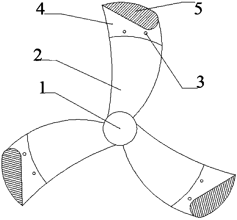
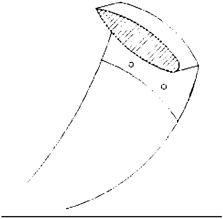
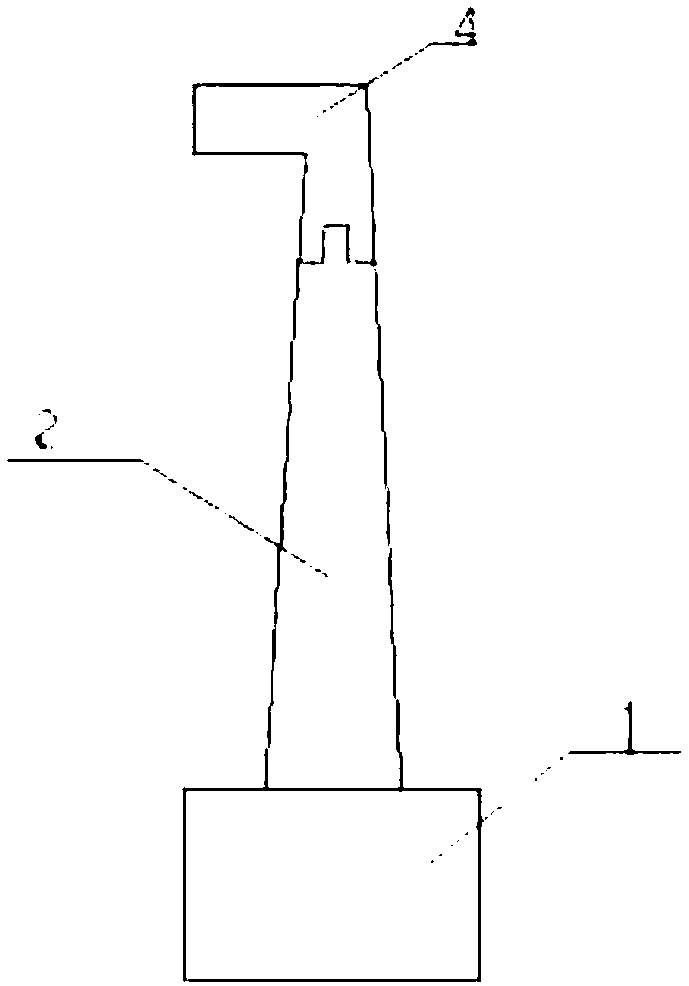
[0016] to combine Figure 1~3 , the present invention is a propeller that reduces the stress at the blade root and reduces the tip vortex, which includes a hub 1, a blade 2, a screw 3, a blade tip leaflet 4 and a transverse flow stop plate 5, the blade tip leaflet 4 and the blade 2 Use mosaic connection and fix it with screw 3.

[0017] See figure 1 , the transverse flow stop plate 5 is fixed on the blade tip leaflet 4, the blade tip leaflet 4 and the transverse flow stop plate 5 are of an integrated structure, the transverse flow stop plate 5 is perpendicular to the blade tip leaflet 4, and the cut surface shape of the transverse flow stop plate 5 is The airfoil is inverted so that when the propeller rotates in the water, it will generate a force directed to the hub, offset the centrifugal force generated by a part of the blades, and reduce the strength require...


PUM


Abstract

The invention aims at providing a propeller for reducing stress at the positions of blade roots and decreasing tip vortexes. The propeller comprises a propeller hub, propeller blades and blade tip small blades. The propeller blades are installed on the propeller hub. Grooves are formed in the end portions of the blade tip small blades. Protrusions matched with the grooves are arranged at the end portions of the propeller blades. The blade tip small blades and the propeller blades are connected in an inlaid manner through the grooves and the protrusions and fixed through screws. The blade tip small blades are provided with transverse flow stop boards, and each transverse flow stop board and the corresponding blade tip small blade are of an integrated structure. By the adoption of the propeller, the centrifugal force generated in the rotation process of the propeller blades can be partially counteracted so that the thickness of each blade root can be reduced, the thrust generated at the positions of the blade roots can be larger, bubbles can be better reduced, and the performance can be optimized. In the rotation process of the propeller, liquid on the blade faces cannot flow to the blade backs, the tip vortexes are decreased, noise is lowered, and larger thrust can be provided through the blade tips.

Description

technical field [0001] The present invention relates to a ship propeller, specifically a propeller. Background technique [0002] Generally, a ship propulsion system includes a ship diesel engine, a shafting system and a propeller. The ship diesel engine generates power and transmits it to the propeller through the shaft system. When rotating, the water flows along both sides of the blade. Due to the asymmetry of the cutting surface of the blade, the speed of the water flowing on both sides is different. According to the Bernoulli equation, it can be known that the pressure difference on both sides of the blade generates thrust. [0003] In the prior art, the speed of the water flow on the blade surface of the propeller is different from that at the back of the blade, and the pressure generated by the water flow on the blade surface and the back of the blade is different, so there will be a pressure difference. Because of this, the propeller generates thrust to work on the s...

Claims


Application Information

Patent Timeline
Patent Type & Authority Patents(China)
IPC IPC(8): B63H1/26B63H1/28
CPCB63H1/26B63H1/28
Inventor 丁宇崔哲随从标王彬赵晨
Owner HARBIN ENG UNIV
Features
  • R&D
  • Intellectual Property
  • Life Sciences
  • Materials
  • Tech Scout
  • Unparalleled Data Quality
  • Higher Quality Content
  • 60% Fewer Hallucinations
Learn More