Electrode bar of electroplating machine roller

A technology of electrode rods and electroplating machines, applied in electrolysis process, electrolysis components, etc., can solve the problems of increased power loss, frequent increase of defective products, insufficient terminal energy, etc., and achieve the effect of reducing production and improving product quality

Active Publication Date: 2016-09-21
珠海瑟泊特科技有限公司
View PDF8 Cites 6 Cited by
  • Summary
  • Abstract
  • Description
  • Claims
  • Application Information

AI Technical Summary

Problems solved by technology

[0004] In order to facilitate installation, usually 0.1-0.2mm is reserved between the self-made binding post holes between the cathode rods. Since electroplating is a low-voltage and high-current mode, in the current connection method, there are There are gaps, and arcs will be generated between the gaps, resulting in heating of the connection parts, surface oxidation, increased resistance, and increased power loss, which will easily lead to insufficient energy provided to the terminal, resulting in changes in the electroplating environment
As a result, the quality of the electroplated products is reduced, the defective products are frequently increased, and the parts need to be disassembled and replaced frequently, which reduces the production efficiency

Method used


Image

  • Electrode bar of electroplating machine roller
  • Electrode bar of electroplating machine roller
  • Electrode bar of electroplating machine roller

Examples


Embodiment Construction

[0026] Now in conjunction with the accompanying drawings, the preferred embodiments of the present invention will be described in detail.

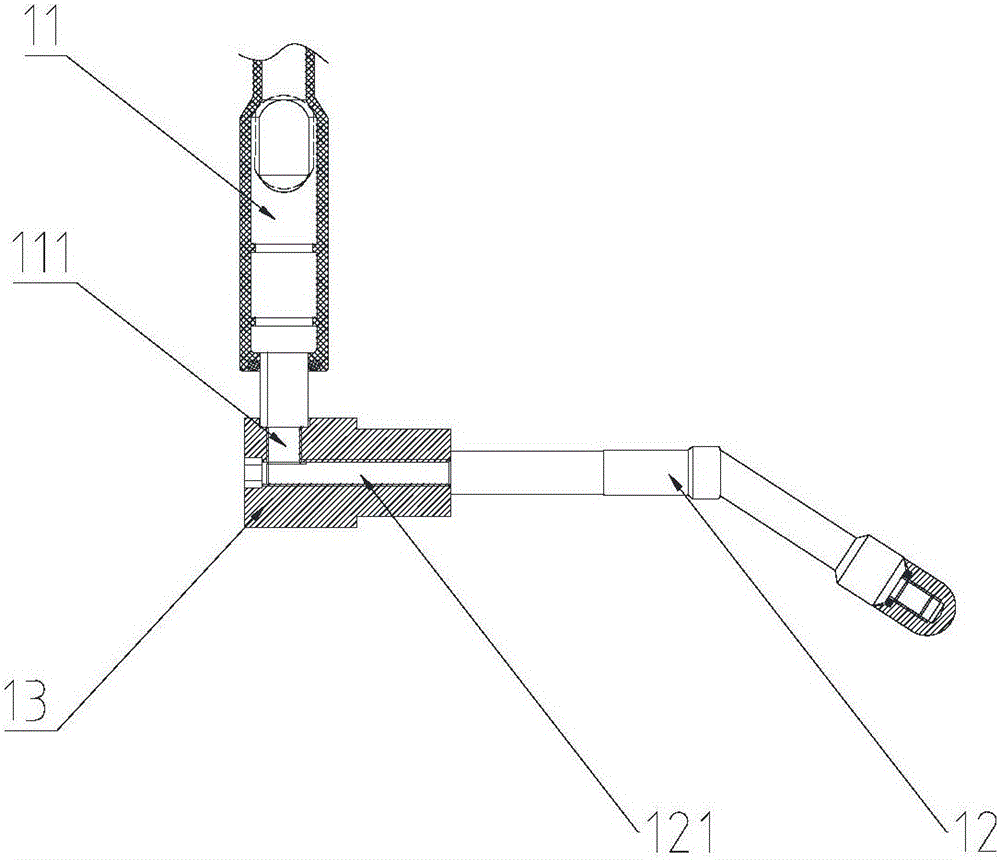
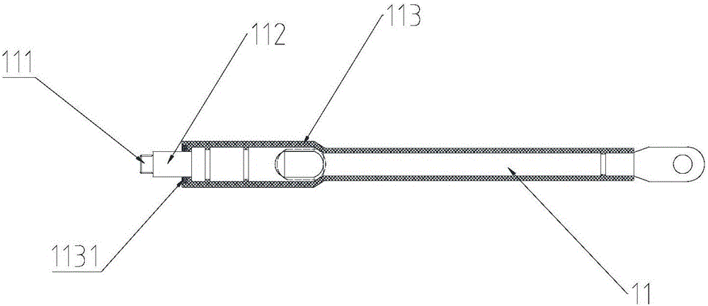
[0027] Such as figure 1 and figure 2 As shown, the present invention provides a preferred embodiment of an electrode rod for an electroplating machine drum.

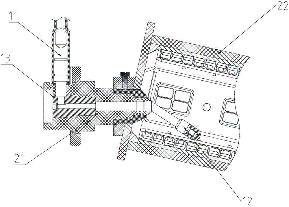
[0028] An electrode rod for an electroplating machine drum. The electroplating machine drum includes a support shaft 21 and a drum 22. The electrode rod is passed through the cavity of the support shaft 21 and extends into the cavity of the drum 22. One end of the electrode rod is connected to an external flexible cable (not shown in the drawings) connection, the electrode rod is used to transfer the flexible cable to the cavity of the drum 22.

[0029] Wherein, the cylinder 22 is rotatably arranged on the support shaft 21, and the cylinder 22 rotates around the support shaft 21. The cylinder 22 includes an eccentric electroplating cylinder 22 and a horizontal electroplating cylin...


PUM


Abstract

The invention relates to the field of electroplating machine rollers and particularly relates to an electrode bar of an electroplating machine roller. The electrode bar comprises a conductive bar, a cathode bar and a support fixed seat, wherein one end of the conductive bar is connected with an external flexible cable, and a first fine thread connecting part is arranged at the end part of the other end of the conductive bar; one end of the cathode bar is arranged in a cavity of the roller, and a second fine thread connecting part in fit connection with the first fine thread connecting part is arranged at the end part of the other end of the cathode bar; and both the first fine thread connecting part and the second fine thread connecting part are arranged in the support fixed seat. According to the electrode bar of the electroplating machine roller, designed by the invention, the support fixed seat is arranged between the conductive bar and the cathode bar, the conductive bar is connected with the cathode bar through threads, and the support fixed seat separately adjoins with the conductive bar and the cathode bar, so that no connecting gaps are left among the conductive bar, the support fixed seat and the cathode bar, and a stable technical environment is provided for electroplating process.

Description

technical field [0001] The invention relates to the field of electroplating machine drums, in particular to an electrode rod for an electroplating machine drum. Background technique [0002] In the prior art, in order to meet the requirements of the electroplating process for small and micro-chip electronic components, most of the cathode circuits of the cylinder of the electroplating machine for chip electronic components are connected to the outside of the cylinder by flexible cables due to the restriction of the space of the cylinder. One or more sections of hard conductive rods, 90-degree or multi-angle terminal terminals are transferred to the cathode rods in the drum cavity. Due to the requirements of the electroplating process, most of the electrode rods need to be sealed in the engineering plastic support shaft cavity, and only the exposed cathode rods The end portion of the plate is plated in a plating drum. [0003] At present, electroplating is mainly carried out...

Claims


Application Information

Patent Timeline
Patent Type & Authority Applications(China)
IPC IPC(8): C25D17/16
CPCC25D17/16
Inventor 杨智华张勇
Owner 珠海瑟泊特科技有限公司
Why Eureka
Try Eureka