Secondary speed reduction barrier gate machine core transmission mechanism with transverse motor

A two-stage deceleration, transverse motor technology, applied in the direction of transmission, transmission parts, gear transmission, etc., can solve the problems of complex overall structure, affecting operation, occupying too much space, etc., to reduce the installation of end caps, avoid power Loss, the effect of fast transmission response

Inactive Publication Date: 2016-09-21
GUANGDONG ANKUAI INTELLIGENT TECH CO LTD
View PDF7 Cites 1 Cited by
  • Summary
  • Abstract
  • Description
  • Claims
  • Application Information

AI Technical Summary

Problems solved by technology

First, the motor is installed vertically below the reduction box, which is likely to cause oil leakage. Since the output shaft of the motor penetrates from the bottom of the reduction box, after a long period of operation, the fit must not be tight enough, and the oil will leak from the gap , affecting operation and leaving potential safety hazards
Second, the deceleration structure of the reducer itself is unreasonable, and a transfer device must be installed to connect with the motor, and a multi-stage gear set is used for deceleration, which has low efficiency, high energy consumption, and high noise, making it difficult to guarantee the working performance
Third, the overall structure of the transmission mechanism of the traditional barrier gate movement is complicated, resulting in a large volume, which brings inconvenience to the application and installation, and ultimately leads to the barrier gate products not being compact enough and taking up too much space
All in all, there are still many unreasonable places in the traditional drive mechanism of the barrier gate, and a new technical solution needs to be proposed to avoid the above-mentioned shortcomings

Method used


Image

  • Secondary speed reduction barrier gate machine core transmission mechanism with transverse motor

Examples


Embodiment Construction

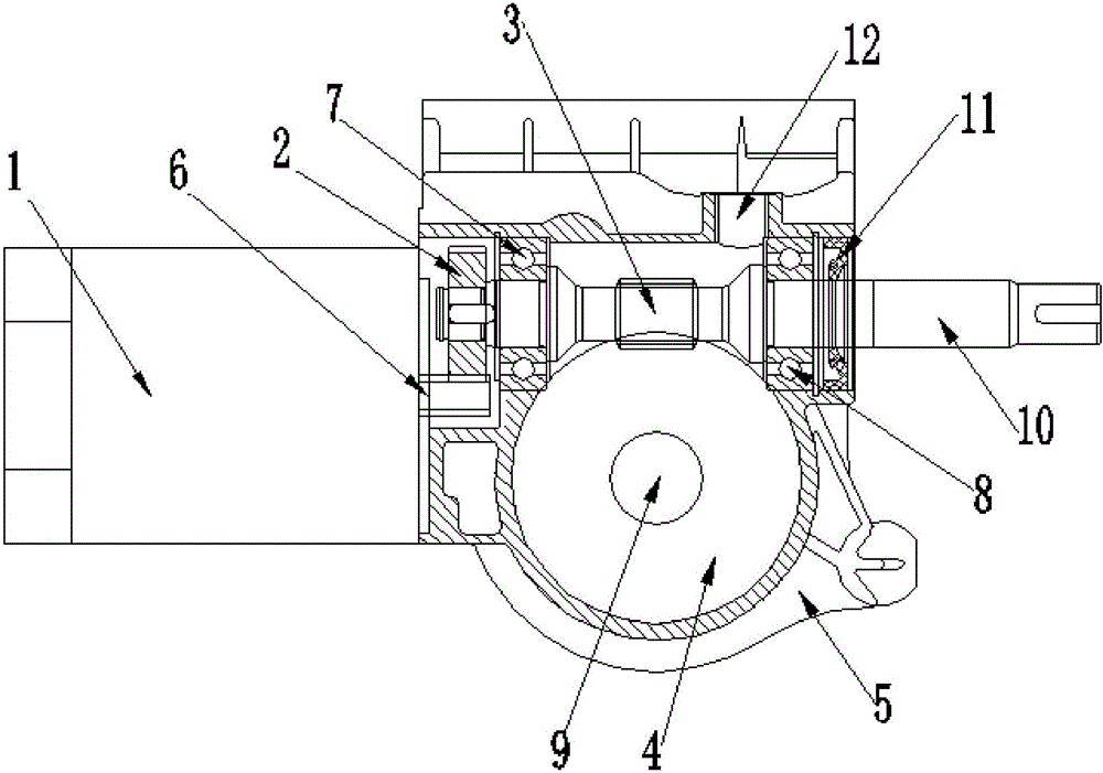
[0015] see figure 1 , The transmission mechanism of the horizontal motor two-stage deceleration gate movement provided by this embodiment includes a motor 1 , a transmission gear 2 , a worm 3 , a turbine 4 and a reduction box 5 . The motor 1 is arranged on the side of the reduction box 5, and the transmission gear 2, the worm 3 and the worm gear 4 are arranged inside the reduction box 5; wherein, the motor 1 is arranged laterally, and the output shaft of the motor 1 is connected to the reduction gear through the reduction gear. The transmission gear 2 is matched (here, it should be noted that the output shaft of the motor cooperates with the transmission gear through the reduction gear, which can be equipped with a reduction gear on the output shaft to cooperate with the transmission gear, or the output shaft of the motor 6 The end itself is a reduction gear structure, that is, an integral structure, and then cooperates with the transmission gear 2. This is the method adopted ...


PUM


Abstract

The invention discloses a secondary speed reduction barrier gate machine core transmission mechanism with a transverse motor. The secondary speed reduction barrier gate machine core transmission mechanism comprises a motor, a transmission gear, a worm, a worm wheel and a speed reduction box. The secondary speed reduction barrier gate machine core transmission mechanism is characterized in that the motor is arranged on the side of the speed reduction box; and the transmission gear, the worm and the worm wheel are arranged in the speed reduction box. The motor is transversely arranged, and an output shaft of the motor is matched with the transmission gear through a speed reduction gear, so that a first stage speed reduction assembly is formed. The end of the worm is connected with the transmission gear, and a body of the worm is matched with the worm wheel, so that a second stage speed reduction assembly is formed. The secondary speed reduction barrier gate machine core transmission mechanism with the transverse motor is scientific and reasonable in structure, oil leakage of a speed reducer is avoided, and the secondary speed reduction barrier gate machine core transmission mechanism is high in efficiency, low in energy consumption and small in noise. Moreover, the overall size can be reduced, and the secondary speed reduction barrier gate machine core transmission mechanism occupies a smaller space and is convenient to install.

Description

technical field [0001] The invention relates to a drive mechanism of a barrier gate movement, in particular to a drive mechanism of a transverse motor two-stage reduction barrier gate movement. Background technique [0002] In the traditional drive mechanism of the barrier gate, the motor is vertically installed under the reduction box, and then connected to the reduction box through the output shaft and the transfer device for transmission. This traditional barrier gate movement transmission mechanism has the following deficiencies. First, the motor is installed vertically below the reduction box, which is likely to cause oil leakage. Since the output shaft of the motor penetrates from the bottom of the reduction box, after a long period of operation, the fit must not be tight enough, and the oil will leak from the gap , affecting operation and leaving potential safety hazards. Second, the deceleration structure of the reducer itself is unreasonable. A relay device must b...

Claims


Application Information

Patent Timeline
Patent Type & Authority Applications(China)
IPC IPC(8): E01F13/04F16H1/20F16H57/021F16H57/023F16H57/039F16H57/04
CPCE01F13/04F16H1/203F16H57/021F16H57/023F16H57/039F16H57/0424F16H2057/02034F16H2057/02039F16H2057/0213
Inventor 肖勇善
Owner GUANGDONG ANKUAI INTELLIGENT TECH CO LTD
Why Eureka
Try Eureka