A vertical lifting mechanism of an automatic and semi-automatic wall plastering machine

A vertical lifting mechanism and technology of lifting mechanism, applied in building structure, construction and other directions, can solve the problems of high cost, cumbersome and complicated lifting mechanism, heavy load, etc.

Active Publication Date: 2018-01-19
嘉兴笼列电子商务有限公司
View PDF6 Cites 0 Cited by
  • Summary
  • Abstract
  • Description
  • Claims
  • Application Information

AI Technical Summary

Problems solved by technology

In the latter, due to the heavy load during lifting and the vibration during operation, the design of the lifting mechanism is cumbersome and complicated, the power consumption of the motor of the lifting mechanism is also large, the machine is prone to failure, and the cost is high.
Although the former has a certain improvement over the latter, it does not need to bear the vertical up and down movement of heavy mortar, but it uses a plastering motor in the design of the plastering board mechanism, and the resistance is relatively large during plastering, so the power of the motor is correspondingly large , so the design of the lifting mechanism tends to be complicated and heavy, and the power of the motor is still too large, and both of them need manual or semi-manual operation for the locked positioning of the lifting rod. , manual or semi-manual operation is required to lock the lifting rod in place
In addition, the lifting rod is designed as a telescopic or folding type, the structure is complex and easily damaged, and the cost is high
This just makes the plastering efficiency of the vertical lifting mechanism of various automatic and semi-automatic plastering machines low, complex and heavy, the power consumption of the motor is large, the failure rate is high, and the cost is high

Method used


Image

  • A vertical lifting mechanism of an automatic and semi-automatic wall plastering machine
  • A vertical lifting mechanism of an automatic and semi-automatic wall plastering machine
  • A vertical lifting mechanism of an automatic and semi-automatic wall plastering machine

Examples


Embodiment Construction

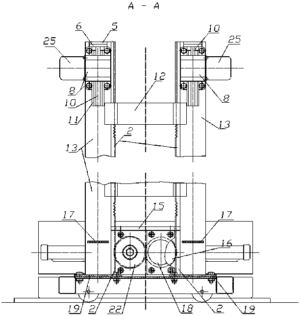
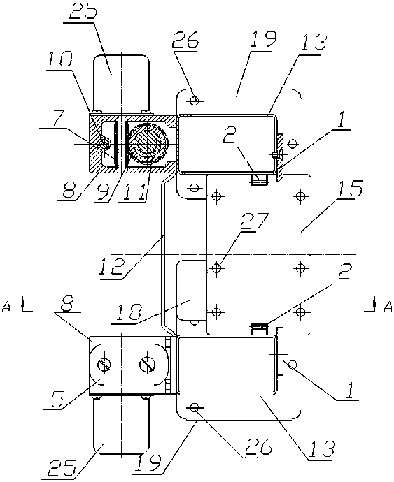
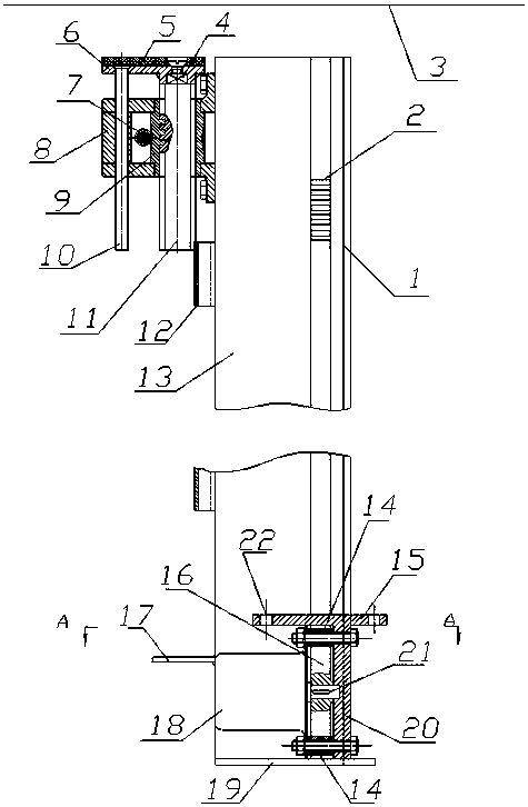
[0017] Such as Figure 3~Figure 6 As shown, a vertical lifting mechanism of a wall automatic semi-automatic plastering machine includes a pair of vertical lifting rods 13 and a lifting mechanism. The vertical lifting rods 13 are a pair of vertical lifting rods 13 with a rectangular cross-sectional shape, and A pair of racks 2 are symmetrically arranged along the vertical height direction of the vertical lifting rod 13 on the inner side outer wall, and a pair of guide rails 1 arranged symmetrically along the vertical height direction of the vertical lifting rod 13 are close to the right pipe wall. The left side between the vertical lifting rods 13 is provided with several pulling rods 12 along the height direction, and the mounting flange 19 that is provided at the bottom of the vertical lifting rods 13 and the reinforcement mounting plate 17 that is provided with near the bottom left pipe wall are both It is used to install the vertical elevating rod 13 on the horizontal platf...


PUM


Abstract

The invention relates to a vertical lifting mechanism for an automatic-semiautomatic wall surface pasting machine in the field of building machinery. The vertical lifting mechanism comprises a pair of vertical lifting rods and a lifting mechanism. The vertical lifting mechanism is characterized in that the sections of the vertical lifting rods are rectangular, a pair of rack are symmetrically arranged on the outer walls of the relative inner sides of the vertical lifting rods along the vertical height direction, a pair of guide rails which are symmetrically arranged along the vertical height direction of the vertical lifting rods cling to the right-side pipe walls, a plurality of traction rods are arranged on the left sides between the pair of the vertical lifting rods along the height direction, mounting flanges are arranged at the bottoms of the vertical lifting rods, reinforcing mounting plates are arranged on the left-side pipe walls close to the bottoms, and automatic lifting rod locking and positioning mechanisms are arranged at the upper parts of the pair of the vertical lifting rods; the lifting mechanism comprises a lifting seat, a lifting motor and a pair of mutually meshed climbing gears. The vertical lifting mechanism has the advantages of simple and light structure, low motor power dissipation, failure rate and cost and high pasting efficiency.

Description

technical field [0001] The invention relates to the field of construction machinery, in particular to a vertical lifting mechanism of an automatic semi-automatic plastering machine for walls. Background technique [0002] In the existing various automatic and semi-automatic plastering machines, some of the plastering methods send the mortar to the plastering board with a hose, spray the mortar to the wall from the ash outlet, and then plaster the plastering board. The mechanism is lifted along the vertical guide rail for plastering; some put the mortar into the ash storage hopper in advance, and the ash storage hopper has an ash outlet facing the wall, and then, the ash storage hopper is lifted along the vertical guide rail while vibrating for plastering. The latter is due to the heavy load during lifting and vibration during work, the lifting mechanism is heavy and complicated in design, the motor power consumption of the lifting mechanism is also large, the machinery is ve...

Claims


Application Information

Patent Timeline
Patent Type & Authority Patents(China)
IPC IPC(8): E04F21/08
CPCE04F21/08
Inventor 李德福
Owner 嘉兴笼列电子商务有限公司
Why Eureka
Try Eureka