Heating pipe positioning structure of pipeline heater for instant drinking water heating device

A pipeline heater and heating device technology, which is applied to fluid heaters, lighting and heating equipment, etc., can solve problems such as affecting normal use, scratching, leakage, etc., and achieve the effect of simple structure and easy implementation.

Inactive Publication Date: 2016-09-21
FOSHAN FOUR SEASONS TEA SET CO LTD
View PDF13 Cites 0 Cited by
  • Summary
  • Abstract
  • Description
  • Claims
  • Application Information

AI Technical Summary

Problems solved by technology

[0002] Existing instant heating devices for drinking water, such as: instant electric water boilers, tea-making appliances and water dispensers with electric heating, etc., most of the heaters used are instant pipeline heaters; traditional pipeline heaters , its structure generally includes a water guide tube and a heating tube. The water guide tube includes a water inlet, a lumen and a water outlet. The heating tube is inserted from one end of the water guide tube and extends into the lumen to the other end close to the lumen. The water in the lumen of the aqueduct is heated, and the heat pipe is inserted into one end of the aqueduct. In order to prevent water leakage, etc., a fixing and sealing mechanism is generally provided, but ...

Method used


Image

  • Heating pipe positioning structure of pipeline heater for instant drinking water heating device
  • Heating pipe positioning structure of pipeline heater for instant drinking water heating device
  • Heating pipe positioning structure of pipeline heater for instant drinking water heating device

Examples


Embodiment Construction

[0023] The present invention will be further described below in conjunction with the accompanying drawings and embodiments.

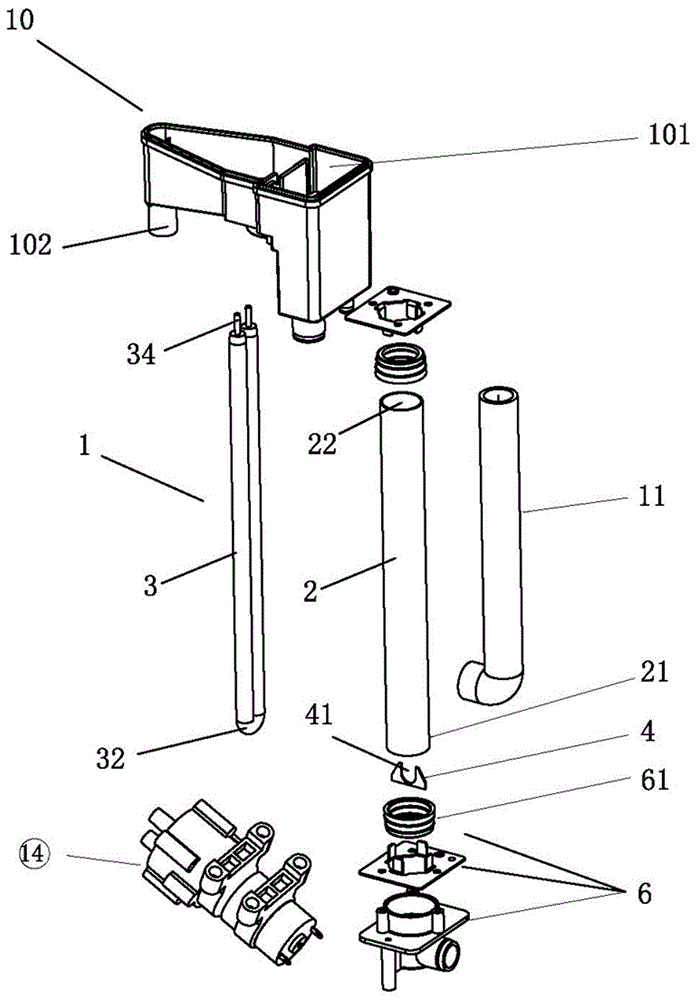
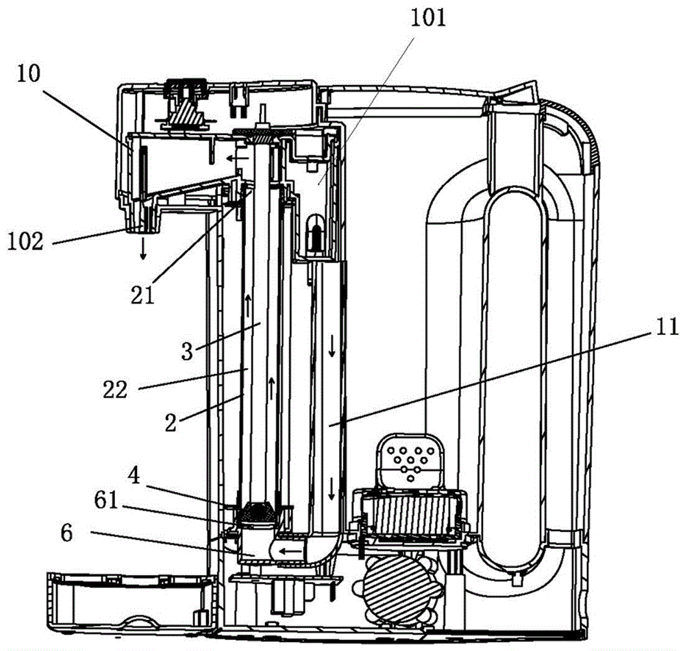
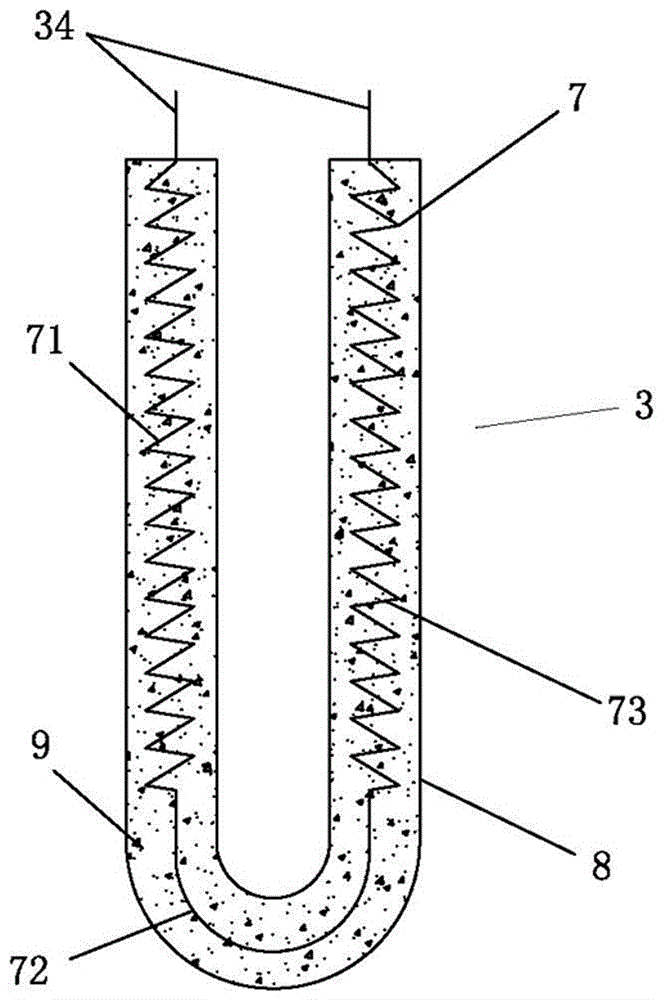
[0024] Such as Figure 1 to Figure 3 As shown, the pipe heater heating pipe positioning structure for the instant drinking water heating device includes a pipe heater 1, the pipe heater 1 includes a water guide pipe 2 and a heat pipe 3, and the water guide pipe 2 includes a water inlet 21, a pipe The cavity 22 and the water outlet 23, the heating tube 3 is inserted into the lumen 22 of the aqueduct 2, and the heating tube 3 heats the water flowing through the aqueduct lumen 22. It is characterized in that the heating tube 3 is provided with a conductive end 34, The conductive end 34 of the heating pipe extends out of the aqueduct 3, and the lumen 22 of the aqueduct 2 is also provided with a positioning block 4, the positioning block 4 clamps the heating pipe 3, so that the heating pipe 3 in the aqueduct 2 is positioned The block 4 is clamped and positi...


PUM


Abstract

The invention relates to a heating pipe positioning structure of a pipeline heater for an instant drinking water heating device. The heating pipe positioning structure of the pipeline heater for the instant drinking water heating device comprises the pipeline heater which comprises a water guide pipe and a heating pipe. The water guide pipe comprises a water inlet, a pipe cavity and a water outlet. The heating pipe is arranged in the pipe cavity of the water guide pipe. The heating pipe is used for heating water flowing through the pipe cavity of the water guide pipe, and the heating pipe is provided with a conductive end. The conductive end of the heating pipe extends out of the water guide pipe. A positioning block is arranged in the pipe cavity of the water guide pipe and used for clamping the heating pipe so that the heating pipe in the water guide pipe can be clamped and positioned in the water guide pipe by the positioning block. According to the heating pipe positioning structure, by simply arranging the positioning block at one end of the heating pipe into the water guide pipe, the end, in the pipe cavity, of the heating pipe is clamped and positioned in the water guide pipe by the positioning block, and the defects that the heating pipe swings in the pipe cavity and even impacts the pipe wall are overcome. In addition, the heating pipe positioning structure is simple and reasonable in structure and easy to implement, the end, in the pipe cavity, of the heating pipe is well protected, and the defects of deformation, damage, electric leakage and the like caused when the heating pipe impacts the pipe wall are overcome.

Description

technical field [0001] The invention relates to an instant drinking water heating device, in particular to a pipe heater heating pipe positioning structure for the instant drinking water heating device. Background technique [0002] Existing instant heating devices for drinking water, such as: instant electric water boilers, tea making appliances and water dispensers with electric heating, etc., most of the heaters used are instant pipeline heaters; traditional pipeline heaters , its structure generally includes a water guide tube and a heating tube. The water guide tube includes a water inlet, a lumen and a water outlet. The heating tube is inserted from one end of the water guide tube and extends into the lumen to the other end close to the lumen. The water in the lumen of the aqueduct is heated, and the heat pipe is inserted into one end of the aqueduct. In order to prevent water leakage, a fixing and sealing mechanism is generally provided, but the other end of the heat ...

Claims


Application Information

Patent Timeline
IPC IPC(8): F24H9/18
CPCF24H9/1818
Inventor 冯海涛
Owner FOSHAN FOUR SEASONS TEA SET CO LTD
Why Eureka
Try Eureka