
Bicycle brake performance test system

A test system, bicycle technology, applied in the direction of vehicle testing, machine/structural component testing, measuring devices, etc., can solve problems such as long coordination time, small detection braking force, poor wear resistance of rollers, etc., to avoid low efficiency problems Effect

Inactive Publication Date: 2016-09-21
INTERTEK TIANJIN QUALITY TECH SERVICES CO LTD
View PDF6 Cites 3 Cited by
  • Summary
  • Abstract
  • Description
  • Claims
  • Application Information

AI Technical Summary

Problems solved by technology

However, the disadvantages of the Japanese-style drum brake test machine are that the repeatability of the detection braking force is poor (poor stability at low speed), the coordination time of the detection is too long, and the detection braking force is small (but it can also be improved by sticking sand on the surface, etc. But the improvement is limited); the disadvantage of the European-style drum brake test machine is that the cost is high; the wear resistance of the drum is worse than that of the cogged drum (the surface is chrome-plated or other wear-resistant treatment), and the service life is about 180,000 times

Method used


Image

  • Bicycle brake performance test system

Examples


Embodiment Construction

[0019] It should be noted that, in the case of no conflict, the embodiments of the present invention and the features in the embodiments can be combined with each other.

[0020] In describing the present invention, it should be understood that the terms "center", "longitudinal", "transverse", "upper", "lower", "front", "rear", "left", "right", The orientations or positional relationships indicated by "vertical", "horizontal", "top", "bottom", "inner", "outer", etc. are based on the orientation or positional relationships shown in the drawings, and are only for the convenience of describing the present invention Creation and simplification of description, rather than indicating or implying that the device or element referred to must have a specific orientation, be constructed and operate in a specific orientation, and therefore should not be construed as limiting the invention. In addition, the terms "first", "second", etc. are used for descriptive purposes only, and should no...


PUM


Abstract

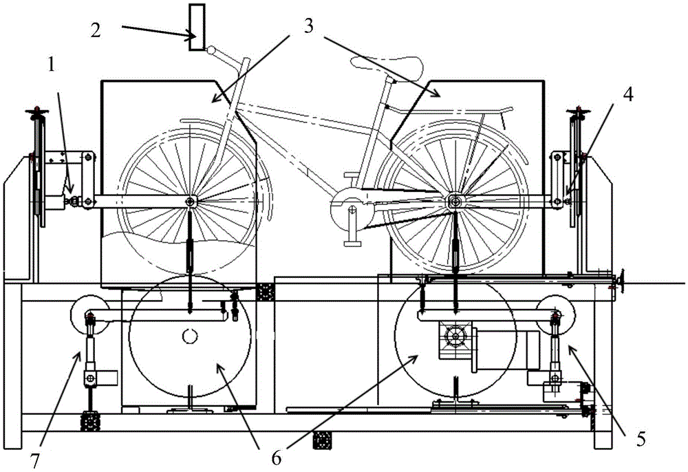
The present invention provides a bicycle brake performance test system. The system comprises a test table, a fixed support, a spray and air blast system and a hand brake motion mechanism which are arranged at the upper portion of the test table, a front-wheel lever-type weight bearing system, a roller and a rear-wheel lever-type weight bearing system. The fixed support is composed of a front support and a rear support and is configured to fix the front and rear wheel of the bicycle; the hand brake motion mechanism is arranged at the upper portion of the brake on the bicycle and is configured to drive the brake motion; a front-brake power sensor is arranged on the position of the front support opposite to the surface of the wheel tire, and a back-brake power sensor is arranged on the position of the rear support opposite to the surface of the wheel tire to measure the motion and the stopping of the tire. The test table employs a dual-roller mode, the test of the braking force of the front and back brakes may be completed only by clamping once, and therefore the problem of low efficiency of the single-roller mode is avoided.

Description

technical field [0001] The invention belongs to the field of automatic testing equipment, and in particular relates to a bicycle braking performance testing system. Background technique [0002] Braking performance is one of the most important items related to safety among the various safety performance indicators of bicycles. It has a direct relationship with the personal safety of riders, and it is also the most complicated item for bicycle theoretical research and the most difficult test. There are two ways to test the braking performance, one is the actual riding road test; the other is to measure the braking force through the testing machine, and then convert the braking distance through the empirical formula. [0003] Among them, the actual riding road test method is more suitable for the actual safety performance requirements, but the actual operation is more difficult, and the magnitude of the applied force and the measurement accuracy of the braking force are greatl...

Claims


Application Information

Patent Timeline
IPC IPC(8): G01M17/007
CPCG01M17/007
Inventor 陈平伟张维童韩文杰孙金阳刘晓菲李冬生
Owner INTERTEK TIANJIN QUALITY TECH SERVICES CO LTD
Learn More