
Outer-hanging touch display device with pressure-sensing touch function

A touch display and touch function technology, which is applied in the field of plug-in touch display devices, can solve the problems of high process difficulty, affect the display quality of the display, complicated structure, etc., and achieve the effects of low production cost, simple structure and easy realization.

Inactive Publication Date: 2016-09-21
WUHAN CHINA STAR OPTOELECTRONICS TECH CO LTD
View PDF5 Cites 6 Cited by
  • Summary
  • Abstract
  • Description
  • Claims
  • Application Information

AI Technical Summary

Problems solved by technology

[0003] But at present, most touch display devices with pressure-sensitive touch function are implemented by adding a plurality of additional pressure sensors in the display (such as a liquid crystal display). This design requires a large change in the structural design of the display itself. And the structure is more complex, the process is more difficult
The pressure sensor has limited spatial resolution, when adding multiple pressure sensors, it will affect the display quality of the display

Method used


Image

  • Outer-hanging touch display device with pressure-sensing touch function
  • Outer-hanging touch display device with pressure-sensing touch function
  • Outer-hanging touch display device with pressure-sensing touch function

Examples


Embodiment 1

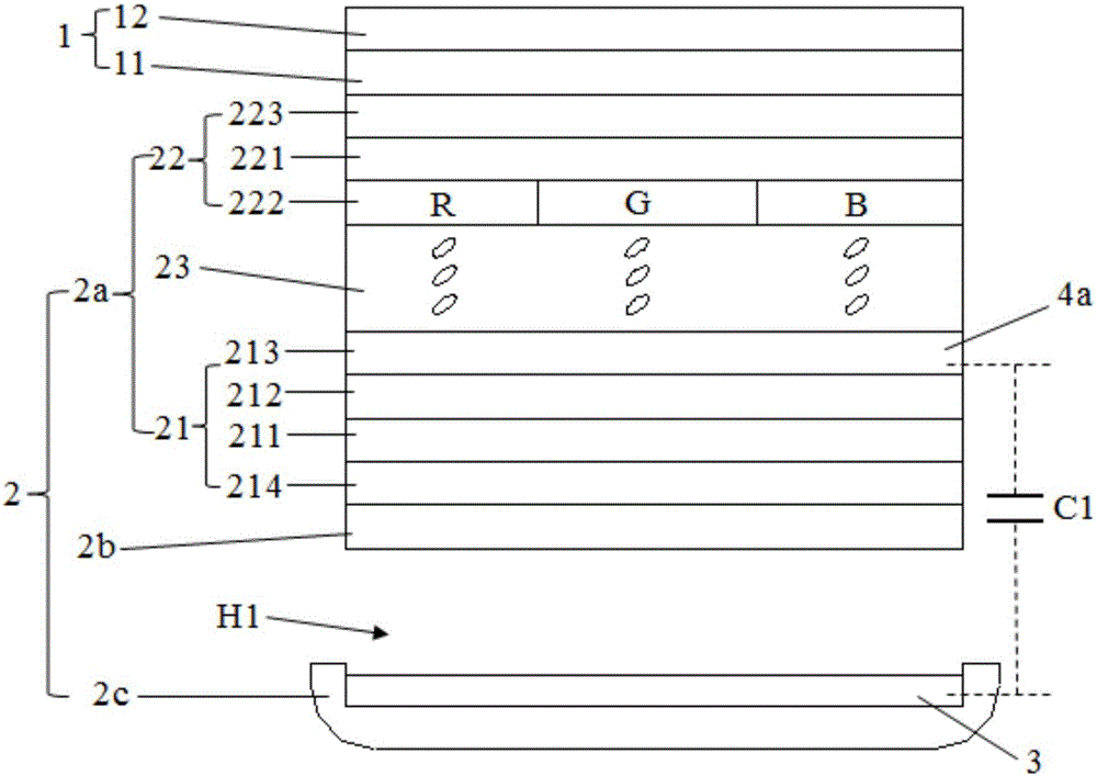
[0024] This embodiment provides an external touch display device with a pressure-sensitive touch function, such as figure 1 As shown, the plug-in touch display device includes a capacitive touch screen 1 and a display module 2 arranged in layers.

[0025] Wherein, the capacitive touch screen 1 includes touch driving electrodes 11 and touch sensing electrodes 12 arranged in different layers, and the touch driving electrodes 11 and touch sensing electrodes 12 are used for sensing touch signals applied on the capacitive touch screen 1 .

[0026] Wherein, the display module 2 includes a display panel 2a and a backlight module 2b arranged oppositely, and a middle frame 2c for supporting the display panel 2a and the backlight module 2b, and the backlight module 2b provides a display light source for the the display panel 2a, so that the display panel 2a displays images.

[0027] Wherein, the display panel 2 a includes an array substrate 21 and a filter substrate 22 disposed opposit...

Embodiment 2

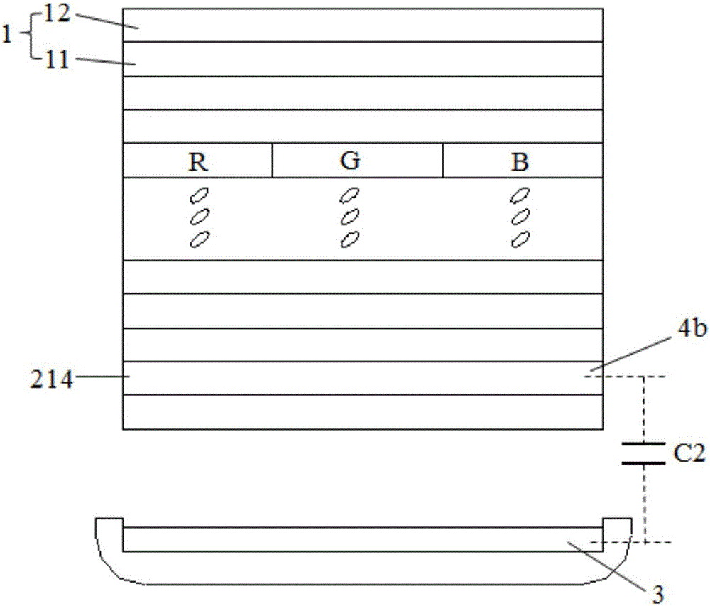
[0032] The difference between this embodiment and embodiment 1 is that, as figure 2 As shown, in this embodiment, the first polarizer 214 is made of a conductive material, and the first polarizer 214 is used as the first capacitance sensing electrode 4b, and the first capacitance sensing electrode 4b and The second capacitive sensing electrode 3 constitutes a capacitive sensing mechanism C2, and the capacitive sensing mechanism C2 is connected with a pressure sensing control chip (not shown in the drawings) for sensing a pressure signal applied to the touch display device.

[0033] Specifically, in the touch display device, the touch control chip drives the touch driving electrodes 11 and the touch sensing electrodes 12 of the capacitive touch screen 1 to sense the touched position. The first capacitive sensing electrode 4b and the second capacitive sensing electrode 3 are driven by the pressure sensing control chip, and when the touching finger presses the capacitive touch s...

Embodiment 3

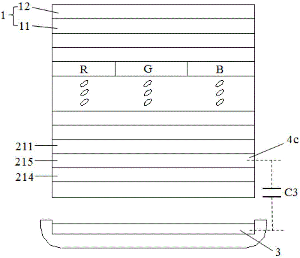
[0035] The difference between this embodiment and embodiment 1 is that, as image 3 As shown, in this embodiment, a first conductive plane 215 is provided between the first polarizer 214 and the first glass substrate 211, and the first conductive plane 215 is used as the first capacitive sensing electrode 4c , the first capacitive sensing electrode 4c and the second capacitive sensing electrode 3 form a capacitive sensing mechanism C3, and the capacitive sensing mechanism C3 is connected with a pressure sensing control chip (not shown in the drawings) for sensing the pressure applied to the touch Displays the pressure signal on the device. Wherein, the first polarizer 214 is made of insulating material, and the material of the first conductive plane 215 is indium tin oxide (ITO).

[0036] Specifically, in the touch display device, the touch control chip drives the touch driving electrodes 11 and the touch sensing electrodes 12 of the capacitive touch screen 1 to sense the tou...


PUM


Abstract

The invention discloses an outer-hanging touch display device with a pressure-sensing touch function. The outer-hanging touch display device comprises a capacitive touch screen and a display module laminated with the capacitive touch screen, wherein the capacitive touch screen is used for sensing touch signals; the display module comprises a display panel, a backlight module opposite to the display panel, and a middle frame; a plurality of conductive structure layers are arranged in the display panel; one of the plurality of conductive structure layers is used as a first capacitive sensing electrode; a second capacitive sensing electrode is arranged on one side, facing toward the backlight module, of the middle frame; a gap is arranged between the second capacitive sensing electrode and the backlight module; and a capacitive sensing mechanism is formed by the first capacitive sensing electrode and the second capacitive sensing electrode, and is used for sensing pressure signals which are applied on the capacitive touch screen. According to the outer-hanging touch display device provided by the invention, a simple structure is used for realizing the pressure-sensing touch function in the touch display device, so that the cost is reduced.

Description

technical field [0001] The invention relates to the field of display technology, in particular to an add-on touch display device with a pressure-sensing touch function. Background technique [0002] With the development and progress of mobile electronic product equipment technology, the use of touch screens is particularly important. At present, there are many different touch sensing technologies, mainly capacitive touch screens, which mainly recognize the plane position information of the finger touch (by obtaining the capacitance changes of the electrodes in the X-axis direction and the Y-axis direction of the point respectively, to accurately calculate location of the touch point). With the continuous improvement of people's requirements for touch technology, the ideal touch screen not only needs to be able to sense the plane position information of touch, but also needs to be able to sense the vertical pressure (Z-axis direction) of touch, so as to realize the tradition...

Claims


Application Information

Patent Timeline
Patent Type & Authority Applications(China)
IPC IPC(8): G06F3/041G06F3/044
CPCG06F3/0414G06F3/044G06F2203/04105G02F1/13338G06F3/0412G06F3/0445G06F3/0447G02F1/133314G02F1/133514G02F1/133528G02F1/133602G06F2203/04112
Inventor 曹昌蔡育徵张洲马长文
Owner WUHAN CHINA STAR OPTOELECTRONICS TECH CO LTD
Learn More