Small-sized unmanned plane camera orientation calibrating device and calibrating method

A small UAV and calibration device technology, applied in image enhancement, image analysis, image data processing, etc., can solve the problem of UAV size, weight, power consumption increase, no camera pan/tilt, no attitude information, etc. Problems, to achieve the effect of improving the accuracy of surveying and positioning, simple components, easy to implement and obtain

Active Publication Date: 2016-09-21
胡碧滢
View PDF5 Cites 12 Cited by
  • Summary
  • Abstract
  • Description
  • Claims
  • Application Information

AI Technical Summary

Problems solved by technology

However, a high-precision gimbal will increase the size, weight, and power consumption of the drone, and the price will be more expensive.
For small UAVs with limited fuselage space, load, and endurance time, it is bound to greatly limit the range of user groups.
[0003] At present, the camera gimbal of small drones does not have accurate attitude information due to low cost and volume and weight limitations. The built-in gimbal auto-calibration function only ensures that the camera is pointing in the horizontal direction, and the vertical ground direction is completely up to the operator. Manually adjust the captured image, and the direct adjustment method is mostly limited to one degree of freedom (pitch), which limits the above-mentioned extended application
That is, there is still no device and method in the prior art that can effectively calibrate the pointing of the camera pan / tilt vertically to the ground

Method used


Image

  • Small-sized unmanned plane camera orientation calibrating device and calibrating method
  • Small-sized unmanned plane camera orientation calibrating device and calibrating method
  • Small-sized unmanned plane camera orientation calibrating device and calibrating method

Examples


Embodiment Construction

[0026] In order to make the object, technical solution and advantages of the present invention clearer, the present invention will be described in further detail below in conjunction with specific embodiments and with reference to the accompanying drawings.

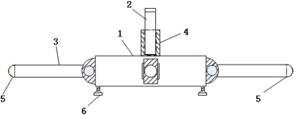
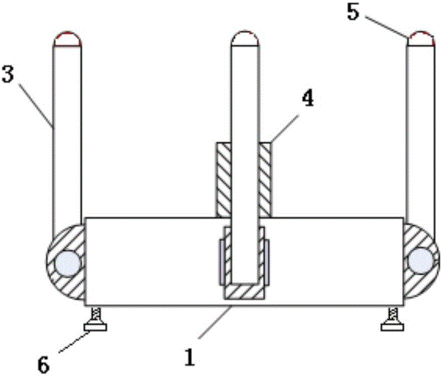
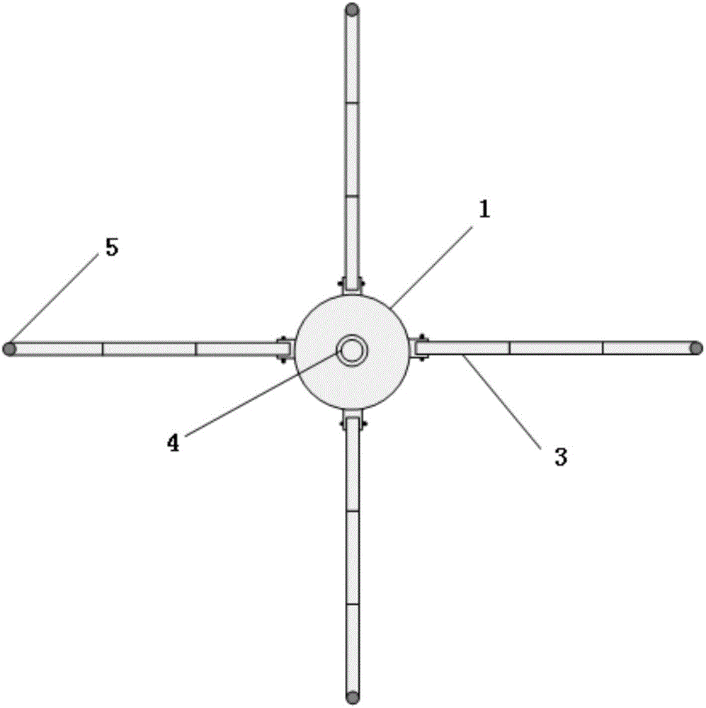
[0027] The embodiment of the present invention provides a low-cost UAV camera pointing calibration device, and establishes a set of UAV camera vertical ground pointing determination methods based on the UAV camera pointing calibration device to support the aerial photography surveying and mapping application of the UAV camera .

[0028] The initial state of the camera gimbal mainly includes pitch (adjustable) and level (rotated by the drone), and the roll direction is determined by the drone's own flight control method. Among them, the pitch direction is the most critical, because the horizontal deviation can be realized by the built-in gimbal automatic calibration function. The method of the embodiment of the present in...


PUM


Abstract

The invention discloses a small-sized unmanned plane camera orientation calibrating device and a calibrating method. The small-sized unmanned plane camera orientation calibrating device comprises a base, a laser pen, and four pull rods. The central position of the upper surface of the base is provided with a laser emission rack, and the laser pen is vertically and fixedly disposed in the laser emission rack. One end of each of the four pull rods is rotatably connected with the side surface of the base, and an included angle between any two pull rods in a horizontal plane is 90degrees. The other ends of the pull rods are provided with mark points having eye-catching colors. The pull rods can be telescoped along an axial direction, and by taking the positions of the rotatable connection between the pull rods and the base as centers, the pull rods are bent upwards, and the states of the axes are changed from the horizontal states to the vertical states. The device provided by the invention is simple in structure, and is convenient in operation, and at the same time, by combing with the calibrating method provided by the invention, the fast and effective calibrating process of the orientation of the cradle head of the camera of the small-sized unmanned plane vertical to the ground is realized.

Description

technical field [0001] The invention relates to the technical field of unmanned aerial vehicle applications, in particular to a small unmanned aerial vehicle camera pointing calibration device and calibration method. Background technique [0002] With the continuous development of drone technology, the cost of drones is getting lower and lower, and the application range is wider and wider. On the basis of common aerial photography functions, through simple expansion, some small UAVs (such as DJI's Phantom 3) can also be expected to achieve low-precision mapping and positioning of objects of interest in the scene. A typical application is to map the appearance of a large building on the ground. The basic principle is: on the premise of knowing the GPS position parameters of the drone, calculate the number of pixels that deviate from the center of the image according to the image of the object captured by the camera, and the number of pixels occupied by the object in the imag...

Claims


Application Information

Patent Timeline
Patent Type & Authority Applications(China)
IPC IPC(8): G06T7/00
CPCG06T2207/30244
Inventor 胡碧滢汤慧仪刘曦远
Owner 胡碧滢
Why Eureka
Try Eureka