Check patentability & draft patents in minutes with Patsnap Eureka AI!

Control rod mechanism

A technology of control rods and driving mechanisms, which is applied in the control of nuclear reactions, reactors, and greenhouse gas reduction, etc., to achieve the effects of height reduction, high safety, and increased safety.

Pending Publication Date: 2016-09-21
SHANGHAI NUCLEAR ENG RES & DESIGN INST CO LTD
View PDF0 Cites 6 Cited by
  • Summary
  • Abstract
  • Description
  • Claims
  • Application Information

AI Technical Summary

Problems solved by technology

[0004] On the other hand, small reactors require a smaller volume of the entire reactor, while Figure 5 The design of the traditional control rod mechanism shown is one of the constraints that limit the shrinkage of small reactors in the height direction

Method used


Image

  • Control rod mechanism
  • Control rod mechanism
  • Control rod mechanism

Examples


Embodiment Construction

[0022] In order to make the above objects, features and advantages of the present invention more comprehensible, the present invention will be further described in detail below in conjunction with the accompanying drawings and specific embodiments.

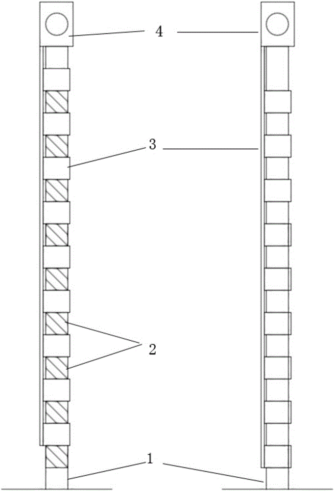
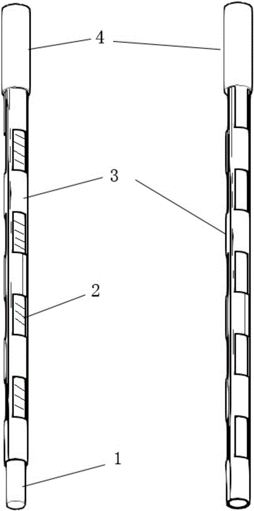
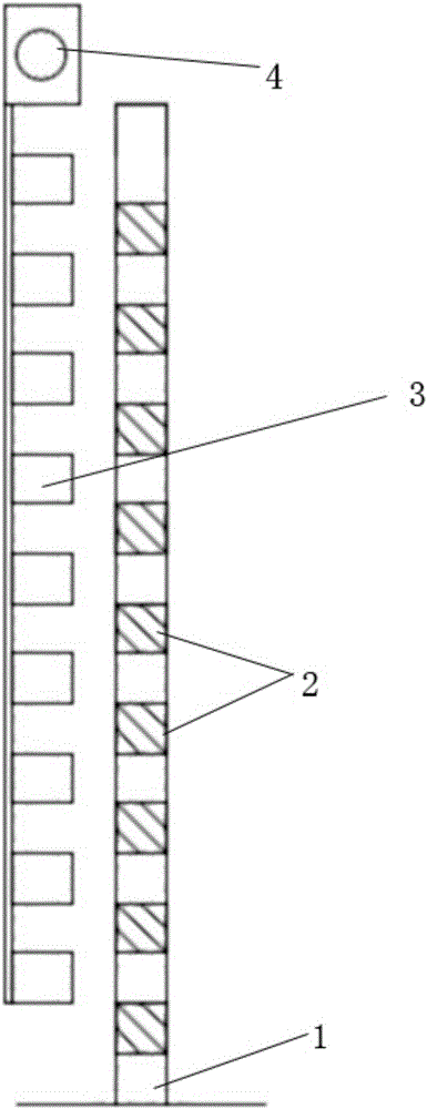
[0023] Such as Figure 1 to Figure 4 As shown, the present invention provides a control rod mechanism, which includes a fixed rod 1, a neutron absorbing material 2, a sliding reflective layer 3, a driving mechanism (not shown) and a pressure-resistant shell 4, wherein: The fixed rod 1 is fixed;

[0024] The neutron absorbing material 2 is uniformly and segmentally arranged on the fixed rod 1;

[0025] The pressure-resistant shell 4 is arranged on the upper end of the fixed rod 1;

[0026] The driving mechanism is arranged on the pressure-resistant shell 4 for driving the sliding reflective layer 3;

[0027] The sliding reflective layer 5 is sleeved on the periphery of the fixed rod 1, including shielding parts and exposed parts...


PUM


Abstract

The invention provides a control rod mechanism, which comprises a fixed rod, a neutron absorbing material, a sliding reflection layer, a driving mechanism and a pressure-resistant case, wherein the fixed rod is fixed and motionless; the neutron absorbing material is arranged on the fixed rod in a uniform and segmented way; the pressure-resistant case is arranged at the upper end part of the fixed rod; the driving mechanism is arranged on the pressure-resistant case and is used for driving the sliding reflection layer; the sliding reflection layer sheaths the periphery of the fixed rod, and comprises a shielding part and an exposing part which are mutually separated; the sliding reflection layer vertically slides along the fixing rod under the driving of the driving mechanism, so that the neutron absorbing material is shielded or exposed. The control rod mechanism provided by the optimal embodiment has the advantages that the size is small; the stroke is short; the safety is high.

Description

technical field [0001] The present invention relates to a control rod mechanism. Background technique [0002] In nuclear reactor engineering, the control of reactivity is realized through the control rod mechanism. Such as Figure 5 As shown, in the traditional control rod mechanism, the bundles of control rods (usually composed of neutron-absorbing materials) are symmetrically and evenly inserted into the fuel assembly, and the control rod mechanism moves up and down as a whole by driving the bundles of control rods , to achieve reactive control. The design of the traditional control rod mechanism is mainly to arrange as many control rod bundles as possible inside the fuel assembly to provide enough negative reactivity to offset the positive reactivity of the nuclear fuel in the fuel rods, thereby ensuring the safety of the reactor . However, the traditional control rod mechanism has the problems of large volume and long stroke. [0003] For small reactors (electrical ...

Claims


Application Information

Patent Timeline
IPC IPC(8): G21C7/28
CPCG21C7/28Y02E30/30
Inventor 郑明光邱忠明唐特
Owner SHANGHAI NUCLEAR ENG RES & DESIGN INST CO LTD
Features
  • R&D
  • Intellectual Property
  • Life Sciences
  • Materials
  • Tech Scout
  • Unparalleled Data Quality
  • Higher Quality Content
  • 60% Fewer Hallucinations
Learn More