Invisible composite magnetic pole and brushless electromagnetic drive motor

An electromagnetic drive and invisible technology, applied to synchronous motors with stationary armatures and rotating magnets, electric components, magnetic circuit rotating parts, etc., can solve the problems of drive motor efficiency reduction, irreversible demagnetization, power and torque drop, etc. , to achieve the effect of less flux leakage

Inactive Publication Date: 2016-09-21
SHANDONG UNIV OF TECH
View PDF9 Cites 1 Cited by
  • Summary
  • Abstract
  • Description
  • Claims
  • Application Information

AI Technical Summary

Problems solved by technology

[0002] At present, the rotors of the permanent magnet drive motors used in electric vehicles mostly adopt the permanent magnet external embedded structure, such as the existing technology, patent name: brushless DC motor rotor, patent number: ZL200920116549.1, discloses the following technical solutions, including the rotor Iron core, rotating shaft and permanent magnet. The rotor iron core is composed of punched sheets and connected together. The rotating shaft and the rotor iron core are fixedly connected. There are even numbers of T-shaped wedges evenly distributed on the outer surface of the rotor iron core. Adjacent T-shaped wedges Slots are formed between the blocks, and the permanent magnets are correspondingly embedded in the slots. The permanent magnets of the rotor with this structure directly face the air gap. Under the action of the armature reaction of the impact current, irreversible demagnetization may occur. Once the permanent magnets form irreversible demagnetization, The efficiency of the driving motor is reduced, and the power and torque drop rapidly, and its performance needs to be further improved

Method used


Image

  • Invisible composite magnetic pole and brushless electromagnetic drive motor
  • Invisible composite magnetic pole and brushless electromagnetic drive motor

Examples


Embodiment Construction

[0011] The present invention will be further described below in conjunction with accompanying drawing:

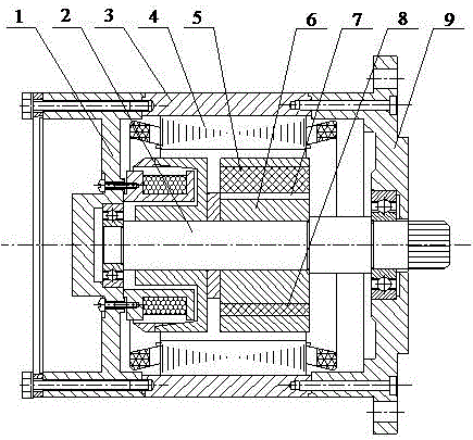
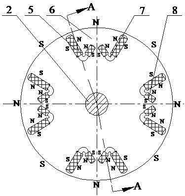
[0012] Invisible compound magnetic pole and brushless electromagnetic drive motor is composed of front cover 9, rear end cover 1, casing 3, hybrid excitation rotor and stator 4, and its characteristic is that the hybrid excitation rotor is made of claw pole motor with brushless slip ring structure. Composed of excitation rotor and invisible compound pole rotor;

[0013] The invisible compound magnetic pole rotor is composed of shaft 2, first rectangular permanent magnet steel 5, second rectangular permanent magnet steel 8, rotor core 6, magnetic isolation air gap 7, and rotor core 6 is evenly distributed with multiple through rotor cores 6 thickness and an inverted "eight" shaped slot formed by two first rectangular slots, the inner end of the inverted "eight" shaped slot formed by the two first rectangular slots is provided with a rotor core 6 thickness and formed by two s...


PUM


Abstract

The invention provides an invisible composite magnetic pole and brushless electromagnetic drive motor, and belongs to the technical field of electric automobile motors and appliances. The drive motor is composed of a front end cover, a rear end cover, a case, a rotor, and a stator. Rectangular permanent magnet steel pieces are respectively embedded into first rectangular slots and second rectangular slots. The permanent magnet steel pieces can be effectively prevented from generating irreversible demagnetization under the armature reaction effect of impact current, and that the permanent magnet steel pieces do not lose magnetism is ensured. The magnetic field in the air gap of the drive motor is provided jointly by the permanent magnet steel pieces and an electric excitation winding. The generated magnetic field directly faces the air gap, and there is less magnetic flux leakage.

Description

technical field [0001] The invention provides an invisible compound magnetic pole and a brushless electromagnetic drive motor, which belongs to the technical field of electric vehicle motors and appliances. Background technique [0002] At present, the rotors of the permanent magnet drive motors used in electric vehicles mostly adopt the permanent magnet external embedded structure, such as the existing technology, patent name: brushless DC motor rotor, patent number: ZL200920116549.1, discloses the following technical solutions, including the rotor Iron core, rotating shaft and permanent magnet. The rotor iron core is composed of punched sheets and connected together. The rotating shaft and the rotor iron core are fixedly connected. There are even numbers of T-shaped wedges evenly distributed on the outer surface of the rotor iron core. Adjacent T-shaped wedges Slots are formed between the blocks, and the permanent magnets are correspondingly embedded in the slots. The perm...

Claims


Application Information

Patent Timeline
Patent Type & Authority Applications(China)
IPC IPC(8): H02K21/14H02K21/04H02K1/27H02K1/24
CPCH02K1/243H02K1/2773H02K21/044H02K21/14H02K2201/03
Inventor 李东兴张学义马世伦王静高艳红
Owner SHANDONG UNIV OF TECH
Why Eureka
Try Eureka