Electric vehicle

An electric vehicle, electric power technology, applied in the direction of electric vehicles, electric vehicle charging technology, vehicle components, etc.

Active Publication Date: 2016-09-21
HONDA MOTOR CO LTD
View PDF6 Cites 3 Cited by
  • Summary
  • Abstract
  • Description
  • Claims
  • Application Information

AI Technical Summary

Problems solved by technology

As a result, parts other than the power receiving part of the charging head interfere with the overhead wire, so that the charging part and the overhead wire cannot be contacted.

Method used


Image

  • Electric vehicle
  • Electric vehicle
  • Electric vehicle

Examples


Embodiment Construction

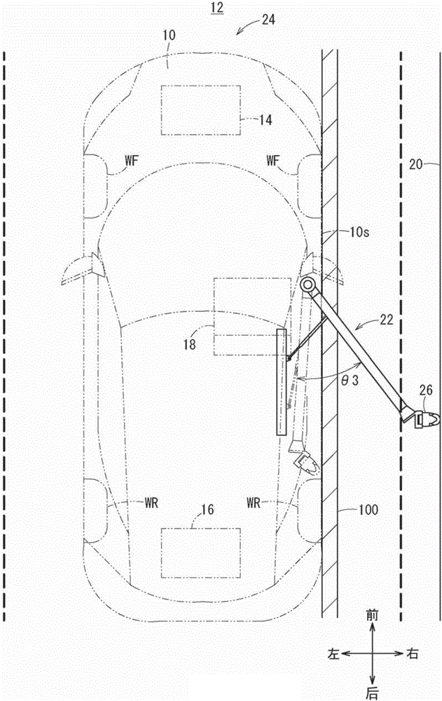
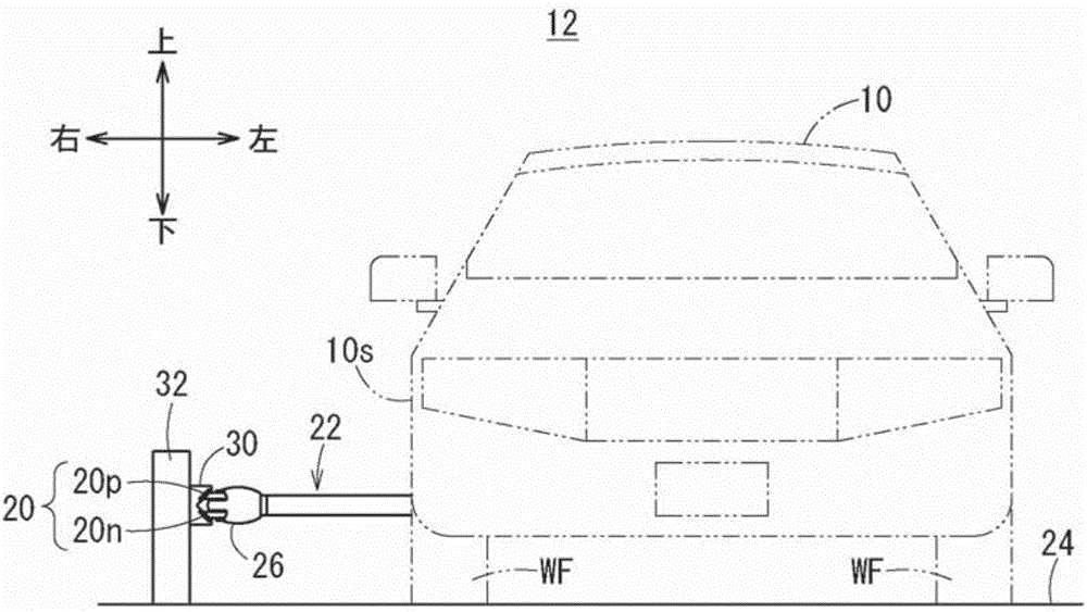
[0026] Hereinafter, an electric vehicle according to the present invention will be described in detail with reference to suitable embodiments and with reference to the drawings.

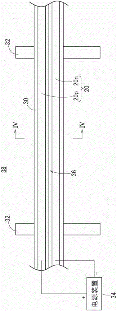
[0027] figure 1 shows a schematic overall structure of the contact charging system 12 when the electric vehicle 10 is viewed from above, figure 2 A schematic overall configuration of the contact charging system 12 is shown when the electric vehicle 10 is viewed from the front. The electric vehicle 10 is a vehicle equipped with an electric motor 14 as a drive source and a driving power storage device 16 for supplying electric power to the electric motor 14, for example, an electric vehicle, a hybrid vehicle equipped with an internal combustion engine, and a fuel cell vehicle. Fuel cell motor vehicles, etc. meet this electric vehicle. It should be noted that, according to figure 1 and figure 2 The directions of the arrows shown will be used to describe the directions of front and rear, left and r...


PUM


Abstract

Provided is an electric vehicle allowing a power receiving portion and an aerial wire to make a stable contact with each other even when the angle formed by a charging head and the aerial wire varies due to the variation of the distance between the electric vehicle and the aerial wire. The electric vehicle (10) charges an electricity storage device (16) by allowing the power receiving portions (40p, 40n) of a charging arm (22) to make contact with an aerial wire (20). In the electric vehicle (10), the charging arm (22) is equipped with an arm portion (86) that is expanded from a side portion (10s) of the electric vehicle (10) toward the outside of the vehicle width by rotationally moving about a rotationally moving shaft (84). The power receiving portions (40p, 40n) are provided on a charging head (26) positioned at the top of the arm portion (86). The charging head (26) is set so as to face the aerial wire (20) in such a direction that the longitudinal direction of the charging head (26) becomes orthogonal to the aerial wire (20) when the arm portion (86) is expanded to a predetermined rotational movement angle (theta3). The arm portion (86) is expanded up to a first rotational movement angle (theta1) larger than the predetermined rotational movement angle (theta3).

Description

technical field [0001] The present invention relates to an electric vehicle that charges a power storage device of the electric vehicle by bringing a power supply wire supplied with electric power into contact with a charging head during travel. Background technique [0002] Japanese Patent Application Laid-Open No. 2013-233037 describes that while the electric vehicle is running, the power receiving part (roller part) of the charging head provided at the front end of the arm part of the electric vehicle rotates and contacts with the electric vehicle to which electric power is supplied. Wired contacts are used to charge the power storage device of the electric vehicle. [0003] If the longitudinal direction of the charging head is perpendicular to the overhead wire when the arm is opened, the arm returns to the electric vehicle side with the charging head in contact with the overhead wire when the distance between the electric vehicle and the overhead wire is shortened. The...

Claims


Application Information

Patent Timeline
Patent Type & Authority Applications(China)
IPC IPC(8): B60L5/38B60L5/40B60L11/18B60M7/00
CPCB60L5/36B60L5/38B60M1/30Y02T90/14Y02T10/7072B60L53/16B60L53/35B60L53/36Y02T10/70Y02T90/12H02J7/0045
Inventor 田岛孝光野口涉
Owner HONDA MOTOR CO LTD
Why Eureka
Try Eureka