

Method for manufacturing thermoelectric conversion element and thermoelectric conversion element
A thermoelectric conversion and manufacturing method technology, which is applied in the manufacture/processing of thermoelectric devices, thermoelectric device components, thermoelectric device node lead-out materials, etc., can solve the problems of increased cost of thermoelectric conversion components, achieve excellent thermoelectric characteristics, prevent The effect of size deviation
- Summary
- Abstract
- Description
- Claims
- Application Information
AI Technical Summary
Problems solved by technology
Method used
Image

Examples
Embodiment 1
[0053] (Structure of thermoelectric conversion element)
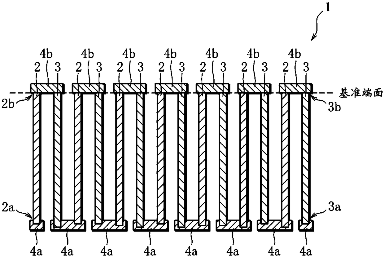
[0054] Below, refer to figure 1 The structure of the thermoelectric conversion element of Example 1 of the present invention will be described. figure 1 It is a cross-sectional view schematically showing the thermoelectric conversion element of Example 1. FIG. in addition, figure 1 is a cross-sectional view along the extending direction of the thermoelectric conversion member constituting the thermoelectric conversion element.
[0055] like figure 1As shown, the thermoelectric conversion element 1 of Example 1 has a first thermoelectric conversion component 2 made of N-type semiconductor material, a second thermoelectric conversion component 3 made of N-type semiconductor material, and the first thermoelectric conversion component 2 and the second thermoelectric Electrodes 4a, 4b joined to both ends of the conversion member 3 . In this embodiment, the first thermoelectric conversion component 2 and the second t...
Embodiment 2
[0076] In the first embodiment described above, the second end portion 2b of the first thermoelectric conversion element 2 and the second end portion 3b of the second thermoelectric conversion element 3 are brought into contact with the bottom surface of the holding part 11 of the manufacturing apparatus 10, whereby , align the second ends 2b, 3b on the same plane, but it is also possible to use Figure 7 The method shown aligns the second ends 2b, 3b on the same plane. Figure 7 With figure 1 A schematic cross-sectional view in the manufacturing process of the thermoelectric conversion element 1 is shown similarly. In addition, except for the process of holding the first thermoelectric conversion member 2 and the second thermoelectric conversion member 3 by the manufacturing apparatus, it is the same as the above-mentioned Example 1, and therefore descriptions other than the holding process are omitted.
[0077] like Figure 7 As shown, the holding part 21 of the manufact...
Embodiment 3
[0083] The thermoelectric conversion element of the present invention is not limited to the thermoelectric conversion element 1 of Embodiment 1 and Embodiment 2 described above, and may be formed by covering the ends of the thermoelectric conversion member with all the electrodes positioned at both ends of the thermoelectric conversion member. That is, all the electrodes may be formed of metal powder. Hereinafter, the thermoelectric conversion element 101 having such a structure will be referred to as Embodiment 3, referring to Figure 8 ~ Figure 14 Its structure and manufacturing method will be described.
[0084] (Structure of thermoelectric conversion element)
[0085] First, refer to Figure 8 The structure of the thermoelectric conversion element 101 according to Example 3 of the present invention will be described. Figure 8 It is a cross-sectional view schematically showing the thermoelectric conversion element of Example 3. FIG. in addition, Figure 8 It is a cros...
PUM
| Property | Measurement | Unit |
|---|---|---|
| diameter | aaaaa | aaaaa |
| length | aaaaa | aaaaa |
Abstract
Description
Claims
Application Information