Alignment device for pipeline welding

A technology of pipes and counterparts, which is applied in the direction of auxiliary devices, welding equipment, auxiliary welding equipment, etc., can solve problems such as heavy workload, hindering welding, and insufficient clamping force, and achieves low misalignment and convenient construction. The effect of welding and rapid welding

Active Publication Date: 2016-09-28
国网冀北电力有限公司管理培训中心 +1
View PDF9 Cites 8 Cited by
  • Summary
  • Abstract
  • Description
  • Claims
  • Application Information

AI Technical Summary

Problems solved by technology

[0003] However, some existing pipeline welding counterparts have complex structures and are not easy to operate. Some pipeline welding counterparts have insufficient clamping force, poor reliability and stability, poor durability, or hinder welding during welding. and other issues, sometimes construction personnel have to make simple tooling and clamping at the construction site to ensure the implementation of butt welding, but they cannot effectively align the nozzles, especially for large-area pipe rows with small pipe diameters and small pipe spacing. Butt welding work, the number of pipes is large, the workload is large, and the working space is small. The current pipe welding counterparts are limited when used in a space with small pipeline gaps, and it is more likely to cause various butt welding defects.

Method used


Image

  • Alignment device for pipeline welding
  • Alignment device for pipeline welding
  • Alignment device for pipeline welding

Examples


Embodiment Construction

[0031] Hereinafter, exemplary embodiments of the present disclosure will be described in more detail with reference to the accompanying drawings. Although exemplary embodiments of the present disclosure are shown in the drawings, it should be understood that the present disclosure may be implemented in various forms and should not be limited by the embodiments set forth herein. On the contrary, these embodiments are provided to enable a more thorough understanding of the present disclosure and to fully convey the scope of the present disclosure to those skilled in the art.

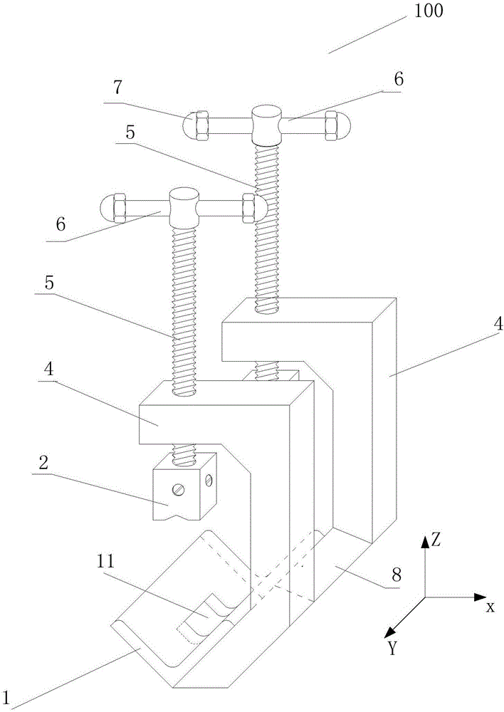
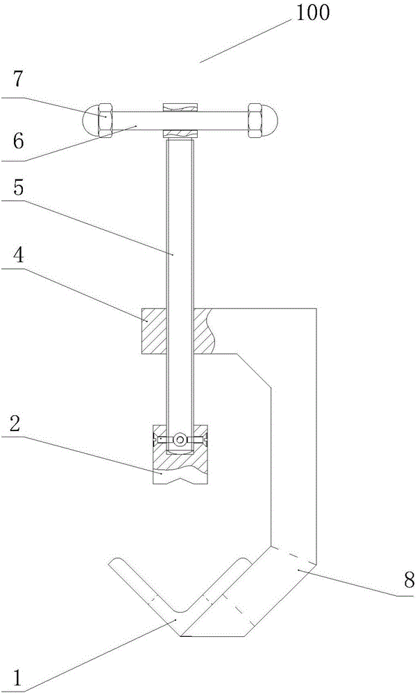
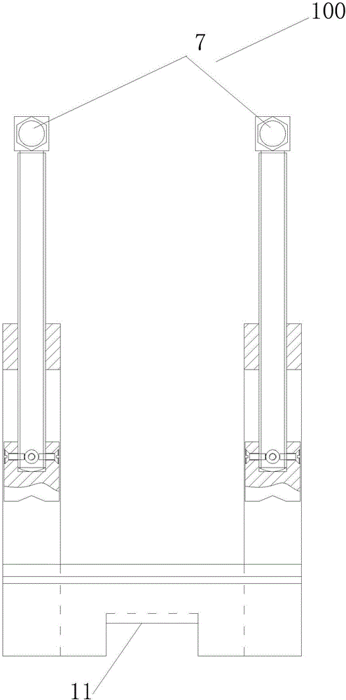
[0032] The invention discloses a pipe welding butt joint device, Figure 1A Shows a schematic structural view of a pipe welding butt device according to an embodiment of the present invention, Figure 1B show Figure 1A The left view of the pipe welding counterpart device shown; Figure 1C show Figure 1A The front view of the pipe welding butt device shown. Such as Figure 1A~1C As shown, the pipe welding align...


PUM


Abstract

The invention provides an alignment device for pipeline welding. The alignment device for pipeline welding comprises two aligner racks, an angular pipeline support and two spiral ejector rods. Each aligner rack is in a handle shape and is provided with a transverse flat upper end, a vertical middle portion and a lower end, wherein the included angle between the lower end and the vertical middle portion is 135 degrees. The angular pipeline support is made of a V-shaped metal material, wherein the included angle between the two planes of the V-shaped metal material is 90 degrees. The angular pipeline support is fixed to the oblique surfaces of the inner sides of the lower ends of the two aligner racks. The two aligner racks are located at the two ends of the angular pipeline support correspondingly. Threaded through holes are formed in the transverse flat upper ends of the aligner racks. The central axes of the threaded through holes are perpendicular to the regression line of the angular pipeline support, and the central axes of the threaded through holes and the regression line of the angular pipeline support are located in the same plane. The spiral ejector rods are rods provided with threads, and the lower ends of the spiral ejector rods penetrate through the threaded through holes in the aligner racks and can be screwed or unscrewed through the threaded through holes. By the adoption of the alignment device for pipeline welding, the end openings of two pipelines can be aligned rapidly, and welding requirements are met.

Description

Technical field [0001] The invention relates to the field of mechanical installation and maintenance, and in particular to a pipe welding butt device used for welding metal tubular objects. Background technique [0002] In the process of construction, installation and maintenance of many projects, butt welding of two pipes with the same diameter is often involved. In order to ensure that the coaxiality (ie, the degree of mutual alignment) of the pipeline (especially the long-distance transportation pipeline) in the butt welding meets the requirements of the specification, and avoid defects such as misalignment or pipeline folds that cause additional stress and affect the life of the pipe, pipes are usually used The welding aligner aligns the nozzles of the two pipes. [0003] However, some of the existing pipe welding counters are complicated in structure and difficult to operate, and some have insufficient clamping force, poor reliability and stability, poor durability, or hinder...

Claims


Application Information

Patent Timeline
Patent Type & Authority Applications(China)
IPC IPC(8): B23K37/053
CPCB23K37/0533
Inventor 张勇张万利郝进全朱琳
Owner 国网冀北电力有限公司管理培训中心
Why Eureka
Try Eureka