Hydraulic internal mold device for concrete box girder

A concrete box girder and inner mold technology, applied in the direction of ceramic molding core, ceramic molding mandrel, etc., can solve the problems of only about 120°, the inability to realize hydraulic integral demoulding, and the difficulty of integral hydraulic demoulding, etc., to achieve The effect of increasing the shrinkage, reducing the labor intensity of construction, and saving the occupied space

Active Publication Date: 2016-09-28
HUNAN WUXIN MACHINERY
View PDF8 Cites 5 Cited by
  • Summary
  • Abstract
  • Description
  • Claims
  • Application Information

AI Technical Summary

Problems solved by technology

When the size of the cavity space in the beam body is small or the concrete thickness at the end is large, it is difficult to realize the overall hydraulic demoulding with the existing internal mold device
[0004] Because the current common box girder hydraulic internal mold mainly includes formwork system, support system and hydraulic system, the formwork system is divided into several sections on the cross section of the beam body, and the sections are connected by hinges. Due to the limitations of the limitation, the closing angle between two adjacent formworks can only reach about 120° at most, which cannot be contracted to the extreme. Therefore, in the case of small box girders or other end sections with small dimensions, the formwork system in the middle shrinks Finally, it cannot be removed from the end at one time, and the hydraulic overall demoulding cannot be realized. Only semi-automatic or manual demoulding of part of the formwork can be used to demould, which is time-consuming and laborious, and seriously affects the construction efficiency.

Method used


Image

  • Hydraulic internal mold device for concrete box girder
  • Hydraulic internal mold device for concrete box girder
  • Hydraulic internal mold device for concrete box girder

Examples


Embodiment 1

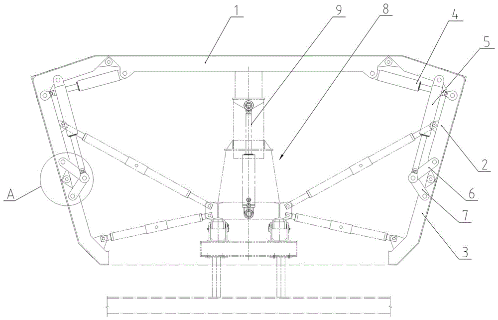
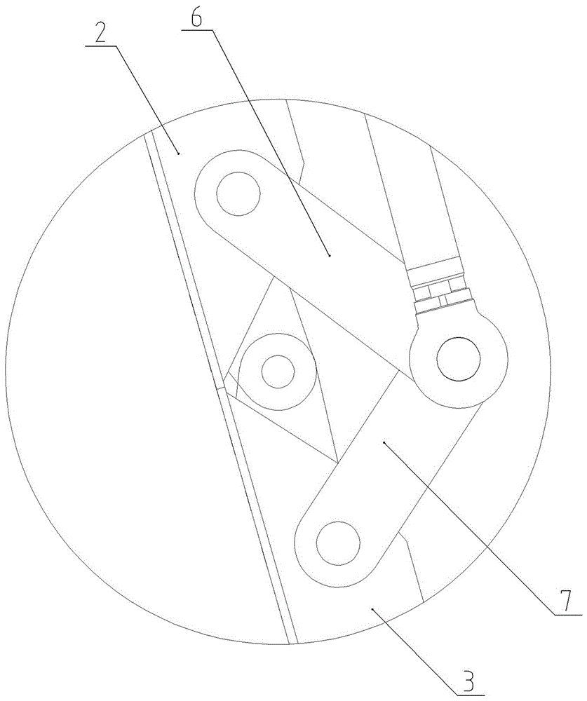
[0024] Embodiment one, such as Figure 1 to Figure 4 As shown, the hydraulic internal formwork device of the concrete box girder disclosed in this embodiment has a formwork system including a top formwork 1 , an upper movable formwork 2 and a lower movable formwork 3 . The upper mold 2 and the lower movable mold 3 are respectively hinged on both sides of the top mold 1 in turn, and a number of hinge seats are respectively arranged on the longitudinal side edges of each template, and the hinge seats between adjacent templates are hinged as a whole through hinge shafts. The top mold 1, the upper movable mold 2 and the lower movable mold 3 enclose the cross-sectional shape of the inner cavity of the concrete box girder.

[0025] An oil cylinder A4 is hinged between the top mold 1 and the upper movable mold 2, and an oil cylinder B5 is hinged between the upper movable mold 2 and the lower movable mold 3.

[0026] The two ends of the oil cylinder A4 and the oil cylinder B5 both ad...

Embodiment 2

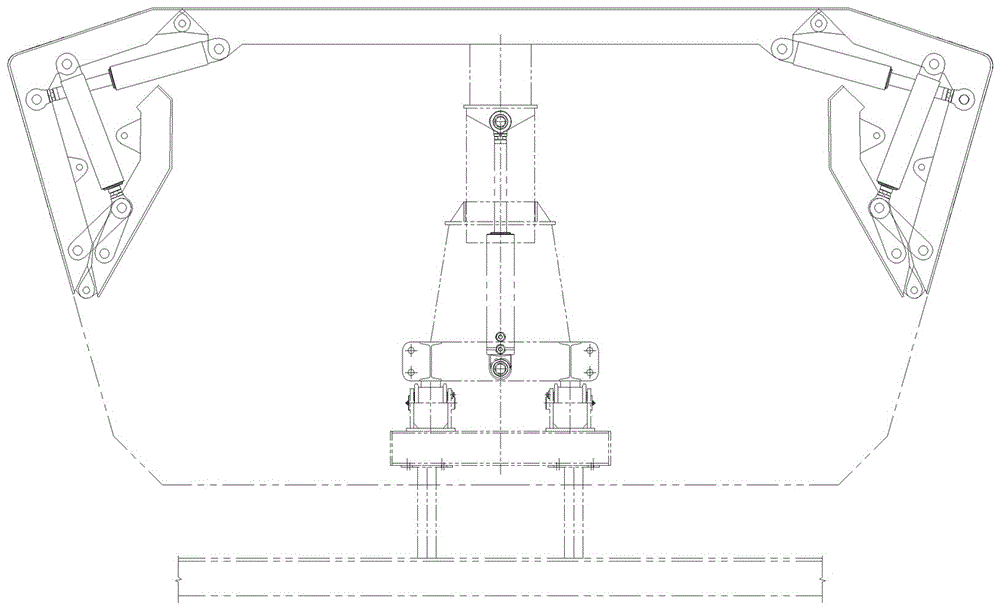
[0039] Embodiment two, such as Figure 5 to Figure 7 As shown, the formwork system of this embodiment includes a top mold and a first upper movable mold 2a, a second upper movable mold 2b and a lower movable mold hinged symmetrically on both sides of the top mold in turn, and the adjacent templates are hinged as a whole. Oil cylinders are respectively hinged between the top mold and the first upper movable mold, between the first upper movable mold and the second upper movable mold, and between the second upper movable mold and the lower movable mold, wherein the first upper movable mold and the second upper movable mold The oil cylinder between the upper moving die is in Figure 5 to Figure 7 None are shown. The hinge position between the two ends of each oil cylinder and the corresponding formwork is based on when the formwork system is folded, the oil cylinder is almost close to the formwork.

[0040] The link mechanism is hinged between the second upper movable mold and ...


PUM


Abstract

The invention discloses a hydraulic internal mold device for a concrete box girder. The device comprises a mold board system and a plurality of oil cylinders; the mold board system comprises a top mold and multiple moving molds sequentially distributed on the left side and the right side of the mold board system, the mold boards are connected through hinges to form an inner cavity shape of the box girder in an enclosing mode, and the oil cylinders are longitudinally hinged between every two mold boards. A connecting rod mechanism is hinged between every two adjacent moving molds, the connecting rod mechanisms and the moving molds hinged to the connecting rod mechanisms together form a multi-rod mechanism, the oil cylinders and the connecting rod mechanism which are arranged between every two adjacent moving molds are hinged into a whole, piston rods of the oil cylinders stretch out to enable the internal mold system to keep the inner cavity shape of the box girder, and the piston rods contract to enable the internal mold system to be closed in a folded mode. Due to the fact that the connecting rod mechanisms and the moving molds are hinged and both can rotate around the joints, strokes of the oil cylinders can be greatly shortened through application of the connecting rod mechanisms; accordingly, the mold board system can be folded and contracted in an inner cavity of the box girder in a large angle, and then one-time integrated demolding of the overall internal mold device can be successfully achieved.

Description

technical field [0001] The invention relates to a concrete box girder, in particular to a hydraulic internal mold device for a concrete box girder. Background technique [0002] With the development of high-speed railway, the whole hole hollow prestressed concrete box girder has been widely used. The box girder hydraulic internal formwork has become one of the necessary large-scale construction equipment in the prefabrication process of the whole hole box girder. When the box girder is prefabricated and poured, the hydraulic inner mold device is used to enclose the corresponding shape of the inner cavity of the box girder. [0003] Due to the requirements of different speeds per hour and different lines of high-speed railways, the girder types of box girders are also varied. When the size of the cavity space in the beam body is small or the concrete thickness at the end is large, it is difficult to realize the overall hydraulic demoulding with the existing internal mold de...

Claims


Application Information

Patent Timeline
Patent Type & Authority Applications(China)
IPC IPC(8): B28B7/30
CPCB28B7/306
Inventor 王祥军郑怀臣夏仙桃谢亮杨波
Owner HUNAN WUXIN MACHINERY
Why Eureka
Try Eureka