Novel continuous mixing machine structure

A kneader and kneading technology, applied in the field of new continuous kneader structure, can solve the problems of inconvenient change of rubber materials, low degree of automation, low production efficiency, etc. High-level, high-efficiency effects

Pending Publication Date: 2016-09-28
DONGGUAN CITY CHANGFENG MECHANICAL TECH CO LTD
View PDF0 Cites 1 Cited by
  • Summary
  • Abstract
  • Description
  • Claims
  • Application Information

AI Technical Summary

Problems solved by technology

[0003] There are various mixing machine structures in the prior art; however, for the existing mixing machines, in the actual use process, there are common problems such as unreasonable design, low degree of automation, low production efficiency, changing rubber, etc. inconvenient defect

Method used


Image

  • Novel continuous mixing machine structure
  • Novel continuous mixing machine structure
  • Novel continuous mixing machine structure

Examples


Embodiment Construction

[0035] The present invention will be described below in conjunction with specific embodiments.

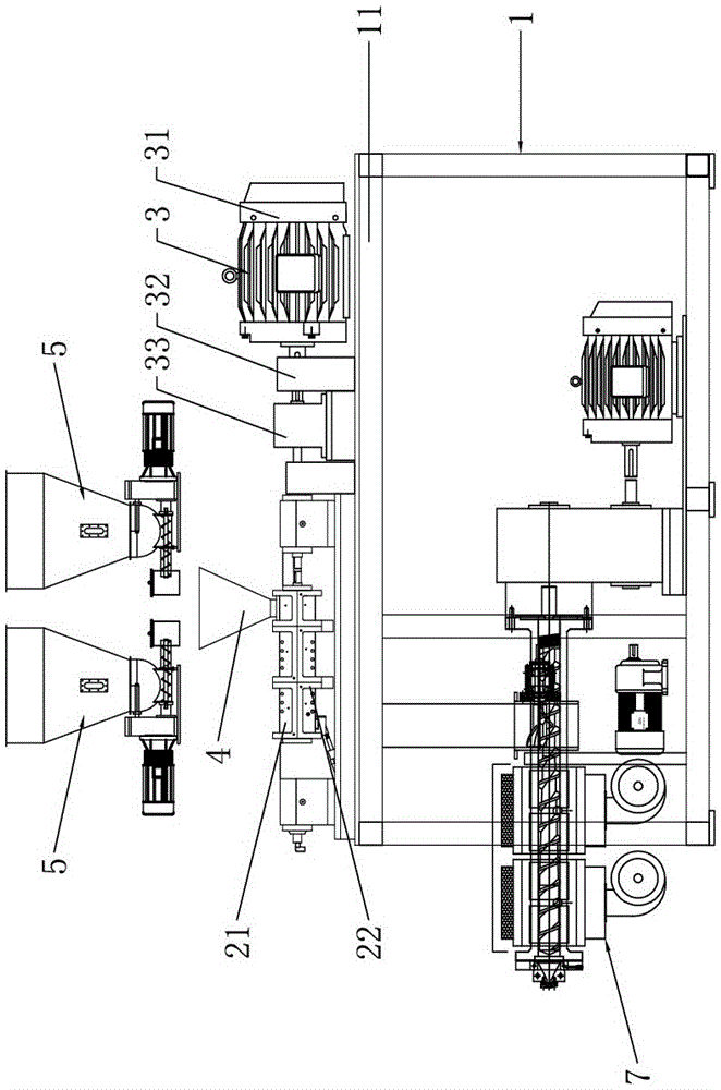
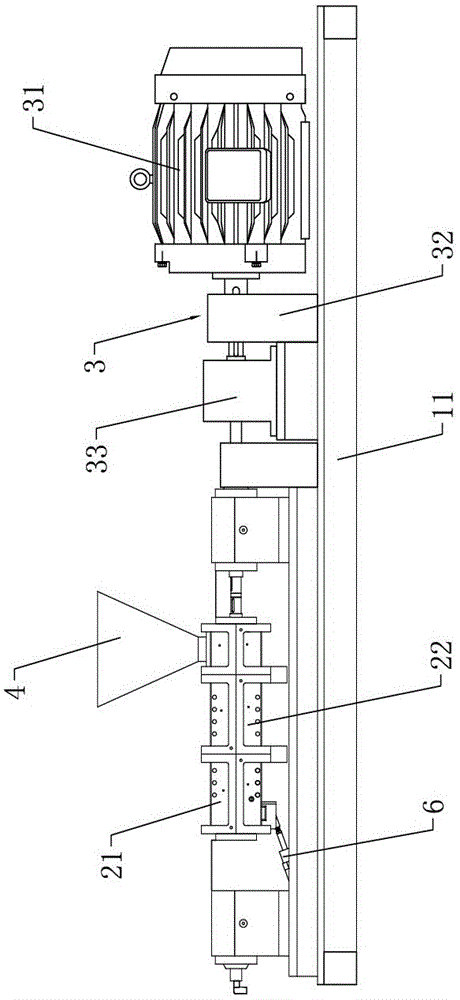
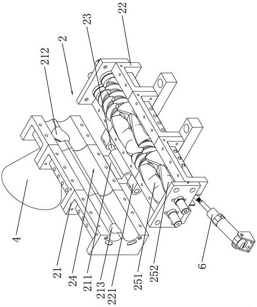
[0036] like Figure 1 to Figure 4 As shown, a new continuous mixer structure includes a frame 1, the upper end of the frame 1 is provided with a fixed support plate 11 arranged horizontally and horizontally, and the upper surface of the fixed support plate 11 is equipped with a mixing host 2 , the mixing host 2 includes a lower mixing shell 22 and an upper mixing shell 21 installed on the upper side of the lower mixing shell 22, the lower mixing shell 22 is screwed to the fixed support plate 11, and the lower mixing The rear surface of the housing 22 is provided with a lower hinged seat 221 protruding backward, and the rear surface of the upper mixing shell 21 is provided with an upper hinged seat 211 protruding backward. The upper hinged seat 211 and the lower hinged seat 221 Hinged by the pivot 23, the mixing host 2 is formed with a mixing chamber 24 in the shape of an inverted ...


PUM


Abstract

The invention discloses a novel continuous mixing machine structure. A mixing main unit is arranged on the upper surface of a fixed supporting plate of a rack, and comprises a lower-end mixing shell and an upper-end mixing shell; a lower-end hinge seat on the rear surface of the lower-end mixing shell is hinged to an upper-end hinge seat on the rear surface of the upper-end mixing shell; a mixing cavity is formed between the upper-end mixing shell and the lower-end mixing shell; a first movable rotor and a second movable rotor are embedded into the mixing cavity and are driven by a rotor driving assembly; a material feeding hopper is arranged at a material inlet in the right end part of the upper-end mixing shell; an automatic feeder is arranged on the upper end side of the material feeding hopper; a material discharging valve is arranged at a material discharging opening in the left end part of the lower-end mixing shell and is driven by a material discharging control cylinder. Due to the structural design, the novel continuous mixing machine structure has the advantages of novel structural design, high automation degree, high production efficiency, continuity of automatic material supplying and convenience in replacement of glue.

Description

technical field [0001] The invention relates to the technical field of material mixing devices, in particular to a novel continuous mixing machine structure. Background technique [0002] As an auxiliary processing device in the plastic molding process, the mixer is widely used in the rubber mixing process; among them, for the mixer, its function is to mix a variety of rubber materials evenly together to Guarantee the quality of follow-up molding. [0003] There are various mixing machine structures in the prior art; however, for the existing mixing machines, in the actual use process, there are common problems such as unreasonable design, low degree of automation, low production efficiency, changing rubber, etc. Inconvenient defects. Contents of the invention [0004] The object of the present invention is to provide a new type of continuous kneader structure in view of the deficiencies of the prior art. The glue is convenient. [0005] In order to achieve the above o...

Claims


Application Information

Patent Timeline
Patent Type & Authority Applications(China)
IPC IPC(8): B29B7/48B29B7/58B29B7/60
CPCB29B7/484B29B7/489B29B7/582B29B7/60B29B7/465B29B7/7495B29B7/603B29C48/682B29B7/488B29B7/748
Inventor 舒飞龙郑家军林涛
Owner DONGGUAN CITY CHANGFENG MECHANICAL TECH CO LTD
Why Eureka
Try Eureka