Rear torsion beam assembly of vehicle

A technology for torsion beams and vehicles, applied in vehicle components, interconnection systems, suspensions, etc., can solve problems such as easy cracking, affecting service life and safety, and achieve the effect of avoiding cracking, solving stress concentration, and improving durability.

Inactive Publication Date: 2016-09-28
CHERY AUTOMOBILE CO LTD
View PDF8 Cites 5 Cited by
  • Summary
  • Abstract
  • Description
  • Claims
  • Application Information

AI Technical Summary

Problems solved by technology

[0002] Most of the torsion beams currently on the market have their main structures welded and formed by stamping parts (such as beam reinforcement plates, hub supports, etc.), and the two ends of the beam reinforcement plates are generally designed to be flat. , stress concentration will occur at one end of the beam reinforcing plate attached to the beam during the torsion process, and stress concentration will also occur in the hub support during the bumping and beating process, both of which are prone to cracking, which will affect the service life and safety

Method used


Image

  • Rear torsion beam assembly of vehicle
  • Rear torsion beam assembly of vehicle
  • Rear torsion beam assembly of vehicle

Examples


Embodiment 1

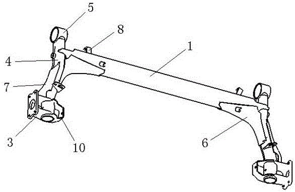
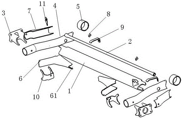
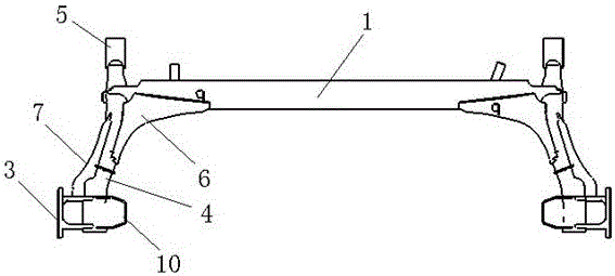
[0023] As shown in the figure, the rear torsion beam assembly of the vehicle in this embodiment includes a crossbeam 1, a torsion bar 2, hub supports 3 on both sides, and a longitudinal arm 4. The front end of the longitudinal arm 4 is provided with a bushing sleeve 5, and the rear end It is welded and fixed with the hub support 3 on the corresponding side; the bushing sleeve 5 is cut from a circular steel pipe, and the front end of the longitudinal arm 4 is cut into an arc shape by machining, so that it can be closely attached to the surface of the bushing sleeve 5; The axis of the bushing 5 is parallel to the beam 1 , which is perpendicular to the trailing arm 4 .

[0024] The two ends of the beam 1 and the torsion bar 2 are respectively welded and fixed to the corresponding side of the longitudinal arm 4, wherein the torsion bar 2 is a solid bar, and the diameter of the torsion bar 2 gradually decreases from the two ends to the middle, and the surface of the torsion bar 2 ha...


PUM


Abstract

The invention aims to provide a rear torsion beam assembly of a vehicle. The rear torsion beam assembly of the vehicle reduces structural stress level and is good in durability. The rear torsion beam assembly of the vehicle comprises a beam, a torsion rod, hub supports on the two sides and trailing arms. The front ends of the trailing arms are provided with bushing sleeves, and the rear ends of the trailing arms are fixedly welded to the hub supports on the corresponding sides. The two ends of both the beam and the torsion rod are fixedly welded to the trailing arms on the corresponding sides respectively. The key is that beam reinforcing plates with arc-shaped sections are welded to the lap joint parts of the beam and the trailing arms, the inner sides of the beam reinforcing plates adhere to the beam and the trailing arms respectively, the front ends of the beam reinforcing plates extend towards the middle of the beam along the beam, and the front ends of the beam reinforcing plates are provided with arc-shaped notches. The rear ends of the beam reinforcing plates extend in the front-end direction of the trailing arms along the trailing arms. The front ends of the beam reinforcing plates are provided with the arc-shaped notches. In the beam torsion process, the arc-shaped notches can effectively reduce the stress level at the position, and thus fracture and the like at the position can be avoided.

Description

technical field [0001] The patent of the present invention relates to the technical field of automobile suspension, in particular to a torsion beam assembly for automobile rear suspension. Background technique [0002] Most of the torsion beams currently on the market have their main structures welded and formed by stamping parts (such as beam reinforcement plates, hub supports, etc.), and the two ends of the beam reinforcement plates are generally designed to be flat. , Stress concentration will occur at one end of the crossbeam reinforcing plate attached to the crossbeam during the torsion process, and stress concentration will also occur in the hub support during the bumping and beating process, both of which are prone to cracking, affecting service life and safety. Contents of the invention [0003] The purpose of the present invention is to provide a vehicle rear torsion beam assembly, which reduces the stress level of the structure and has better durability. [0004...

Claims


Application Information

Patent Timeline
Patent Type & Authority Applications(China)
IPC IPC(8): B60G21/05B60G21/055
CPCB60G21/05B60G21/055
Inventor 程林孙义杰周浩泽杨展宋东奇
Owner CHERY AUTOMOBILE CO LTD
Why Eureka
Try Eureka