An engine compartment longitudinal beam and a front floor longitudinal beam connecting structure and automobile

A technology for front floor longitudinal beams and engine compartments, applied to the connection between superstructure subassemblies, superstructure, vehicle components, etc., can solve the problems of affecting the layout of parts, occupying space, and poor collision transmission paths, etc. Achieve the effect of enhancing structural strength, ensuring structural strength, and optimizing the way to transmit impact force

Active Publication Date: 2016-09-28
CHONGQING CHANGAN AUTOMOBILE CO LTD
View PDF6 Cites 2 Cited by
  • Summary
  • Abstract
  • Description
  • Claims
  • Application Information

AI Technical Summary

Problems solved by technology

This connection structure is provided with a connecting plate, a root reinforcement and a front end reinforcement of the floor beam on one side where the front longitudinal beam of the automobile (that is, the longitudinal beam of the engine compartment in the present invention) overlaps with the front floor longitudinal beam. One side of the overlap between the longitudinal beam and the front floor longitudinal beam forms a reinforced structure, which can only meet the connection strength between the front longitudinal beam and the front floor longitudinal beam to a certain extent, and there is a problem of poor collision transmission path
At the same time, since the connecting plate, the root reinforcement and the front end reinforcement of the floor beam are all located outside the front longitudinal beam and the front floor longitudinal beam of the car, it will occupy space and affect the layout of other parts of the car

Method used


Image

  • An engine compartment longitudinal beam and a front floor longitudinal beam connecting structure and automobile
  • An engine compartment longitudinal beam and a front floor longitudinal beam connecting structure and automobile
  • An engine compartment longitudinal beam and a front floor longitudinal beam connecting structure and automobile

Examples


Embodiment Construction

[0025] The present invention will be further described below in conjunction with accompanying drawing.

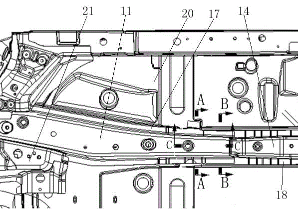
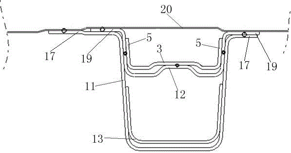
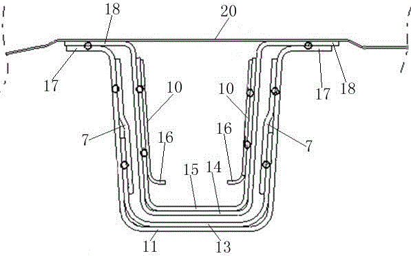
[0026] Such as Figure 1-Figure 4 The connection structure between the engine compartment longitudinal beam and the front floor longitudinal beam is shown, including the engine compartment longitudinal beam 11 and the front floor longitudinal beam 14 arranged along the front and rear directions, and the section of the engine compartment longitudinal beam 11 and the front floor longitudinal beam 14 Both are U-shaped, the rear end of the engine compartment longitudinal beam 11 has a first overlapping section, and the front end of the front floor longitudinal beam 14 has a second overlapping section, the second overlapping section is located in the first overlapping section and the two The two are overlapped together, and the length of the overlapping area of ​​the two is 120mm in the front-to-rear direction; the engine room longitudinal beam 11 is provided with a first reinfo...


PUM


Abstract

The invention relates to an engine compartment longitudinal beam and front floor longitudinal beam connecting structure and an automobile. The connecting structure comprises an engine compartment longitudinal beam and a front floor longitudinal beam, a first lap joint section is arranged on the rear portion of the engine compartment longitudinal beam, a second lap joint section is arranged at the front end of the front floor longitudinal beam, and the second lap joint section is located in the first lap joint section and is in lap joint with the first lap joint section; a first reinforcing part is arranged in the engine compartment longitudinal beam, the rear end of the first reinforcing part is fixedly connected with a support assembly, two first side plates in lap joint with two side plates of the engine compartment longitudinal beam respectively are arranged on the rear portion of the support assembly, and at least one part of each first side plate is located in the first lap joint section; a third support is arranged in the front floor longitudinal beam and comprises a second vertical plate and two second side plates, and the two side plates overlap the two side plates of the front floor longitudinal beam and are fixedly connected with the two side plates. The structural strength of the lap joint region of the engine compartment longitudinal beam and the front floor longitudinal beam can be improved, while requirement for external arrangement space of the lap joint region is not increased.

Description

technical field [0001] The invention relates to an automobile, in particular to a connection structure between an engine compartment longitudinal beam and a front floor longitudinal beam and the automobile. Background technique [0002] At present, the development of new models pays more and more attention to performance development, and the longitudinal beam of the vehicle body is an important part that affects the performance of the vehicle body; It includes front longitudinal beams, connecting plates and front floor longitudinal beams which are welded in sequence, the front part of the reinforcing groove of the connecting plate is overlapped with the rear part of the front longitudinal beams, and the rear part is overlapped with the groove-shaped front floor longitudinal beams. A root reinforcement is welded in the groove of the overlapping part of the connecting plate, and a groove-shaped floor beam reinforcement is stacked on the back of the reinforcement groove of the ...

Claims


Application Information

Patent Timeline
Patent Type & Authority Applications(China)
IPC IPC(8): B62D27/02
CPCB62D27/02
Inventor 赵月欣张晨李可易兵王远宏邹军
Owner CHONGQING CHANGAN AUTOMOBILE CO LTD
Why Eureka
Try Eureka