A repeatable and variable configuration truss spacecraft structure

A spacecraft structure and truss-type technology, applied in the field of aerospace, can solve the problems of fixed and closed spacecraft structure, redundant and complex, difficult to realize the upgrade and maintenance of spacecraft on-orbit maintenance equipment, etc. The effect of large network space ratio and low density

Active Publication Date: 2018-03-16
HARBIN INST OF TECH
View PDF6 Cites 0 Cited by
  • Summary
  • Abstract
  • Description
  • Claims
  • Application Information

AI Technical Summary

Problems solved by technology

[0003] The purpose of the present invention is to provide a truss-type spacecraft structure with repeatable variable configuration to solve the problem that the existing spacecraft has a fixed and closed structure and complex redundancy, and it is difficult to realize on-orbit maintenance and equipment upgrade maintenance of spacecraft failures

Method used


Image

  • A repeatable and variable configuration truss spacecraft structure
  • A repeatable and variable configuration truss spacecraft structure
  • A repeatable and variable configuration truss spacecraft structure

Examples


specific Embodiment approach 1

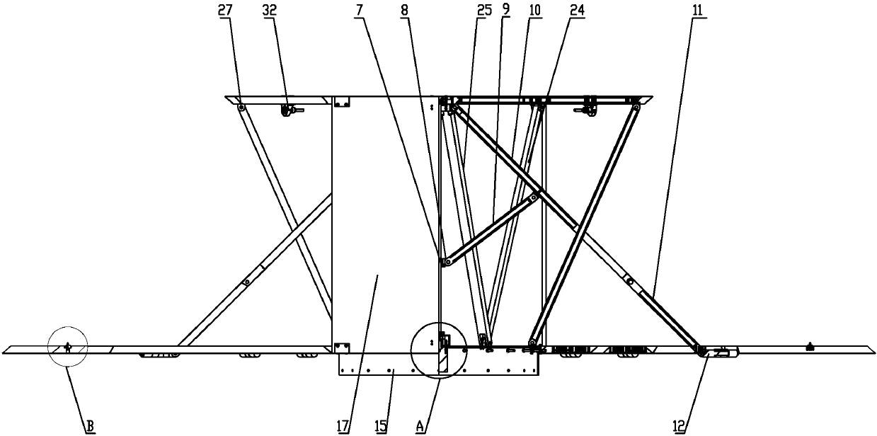
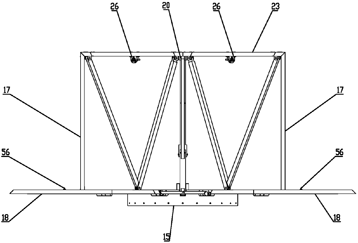
[0028] Specific implementation mode one: combine Figure 1 to Figure 9 Describe this embodiment. This embodiment includes a docking ring 15, a bottom plate 16, a support frame 19, a transmission mechanism, a system drive mechanism, N-4 sets of truss configuration change mechanisms, two fixed support plates 17, and N-2 deployment Plate 18 and N-2 locking mechanisms;

[0029] The docking ring 15 is arranged on the bottom of the bottom plate 16, the system driving mechanism and the support frame 19 are all arranged on the top of the bottom plate 16, the bottom of the transmission mechanism is arranged on the system driving mechanism, and the top of the transmission mechanism is arranged on On the support frame 19, the two fixed support plates 17 are vertically arranged side by side on the support frame 19 and the two are oppositely arranged, and the N-2 expansion plates 18 are hinged at the edge of the bottom plate 16 in turn, and each expansion The plate 18 is correspondingly p...

specific Embodiment approach 2

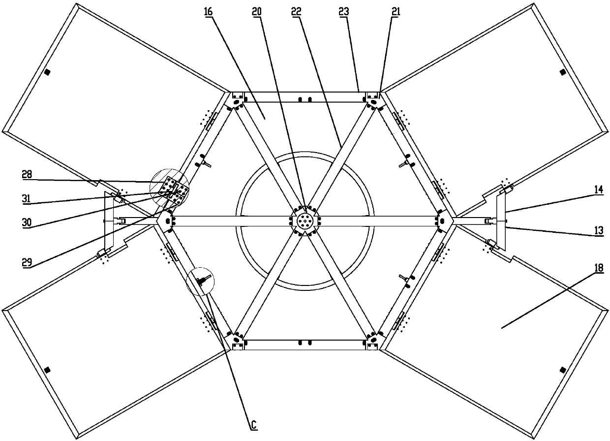
[0032] Specific implementation mode two: combination Figure 1 to Figure 9 To describe this embodiment, the value of N in this embodiment ranges from 6 to 12. When the value of N is 6, there are 2 sets of truss variable configuration mechanisms, 4 expansion plates 18 and 4 locking mechanisms, and the appearance of the present invention in the folded state is a hexagonal prism; when the value of N is At 8 o'clock, there are 4 sets of truss variable configuration mechanisms, 6 expansion plates 18 and 6 locking mechanisms. Prismatic, nine prisms and other prisms.

[0033] The shape of the bottom plate 16 in the present invention is related to the specific value of N. When the value of N is 6, the bottom plate 16 is a hexagonal plate. Other unmentioned structures and connections are the same as those in the first embodiment.

specific Embodiment approach 3

[0034] Specific implementation mode three: combination figure 1 with Figure 4 Describe this embodiment, the system driving mechanism in this embodiment includes a total motor 1, a total reducer 2, a bearing bracket 3, a shaft coupling 4 and a bearing 5, the total motor 1 is arranged on the bottom plate 16, and the The output shaft of the total motor 1 is provided with a total reducer 2 , a bearing bracket 3 , a shaft coupling 4 and a bearing 5 in sequence. Other unmentioned structures and connections are the same as those in the first or second embodiment.


PUM


Abstract

A repeatable variable configuration truss type spacecraft structure relates to a spacecraft. Existing spacecraft have fixed and closed structures and complex redundancy, making it difficult to achieve on-orbit repairs and equipment upgrades for spacecraft failures. In the present invention, the docking ring is arranged on the bottom of the base plate, the system driving mechanism and the support frame are arranged on the top of the base plate, the bottom of the transmission mechanism is arranged on the system drive mechanism, the top of the transmission mechanism is arranged on the support frame, and two fixed support plates They are arranged vertically and side by side on the support frame and oppositely arranged. The bottoms of the N-2 expansion plates are hinged at the edge of the bottom plate in sequence. Each expansion plate is correspondingly provided with a locking mechanism. Every two adjacent expansion plates The panels are connected to the transmission mechanism through a corresponding set of truss configuration-changing mechanisms, and the N-2 unfolded panels are simultaneously unfolded and folded under the control of N-4 sets of truss configuration-changing mechanisms and the transmission mechanism. The invention is used in the aerospace field.

Description

technical field [0001] The invention relates to a variable-configuration truss-type spacecraft structure, which belongs to the field of aerospace. Background technique [0002] With manned spacecraft, space stations, long-lived satellites and other spacecraft operating in orbit for a long time, the future on-orbit service technology has great application prospects. With the increasingly complex structure and larger scale of satellite platforms, traditional satellite platforms have shown great limitations. For example, traditional satellites are mostly closed polyhedrons with unchanged structures. Usually, various subsystems such as thermal control, The integration of communication, attitude control, propulsion and other payloads together, coupled with the increased redundancy design to improve reliability, makes the entire satellite structure complex and difficult to achieve on-orbit maintenance. In short, the existing spacecraft have fixed and closed structures and complex...

Claims


Application Information

Patent Timeline
Patent Type & Authority Patents(China)
IPC IPC(8): B64G1/10B64G1/22
CPCB64G1/10B64G1/222B64G1/223
Inventor 郭宏伟刘荣强邓宗全赵冲岳洪浩
Owner HARBIN INST OF TECH
Why Eureka
Try Eureka