Pneumatic power generating device
A technology of power generation device and air passage, which is applied to engine components, machines/engines, mechanical equipment, etc., can solve the problems of high production cost of driving wheels, unsatisfactory power generation, poor impact resistance, etc. The effect of improving processing and pressure resistance
- Summary
- Abstract
- Description
- Claims
- Application Information
AI Technical Summary
Problems solved by technology
Method used
Image

Examples
Embodiment 1
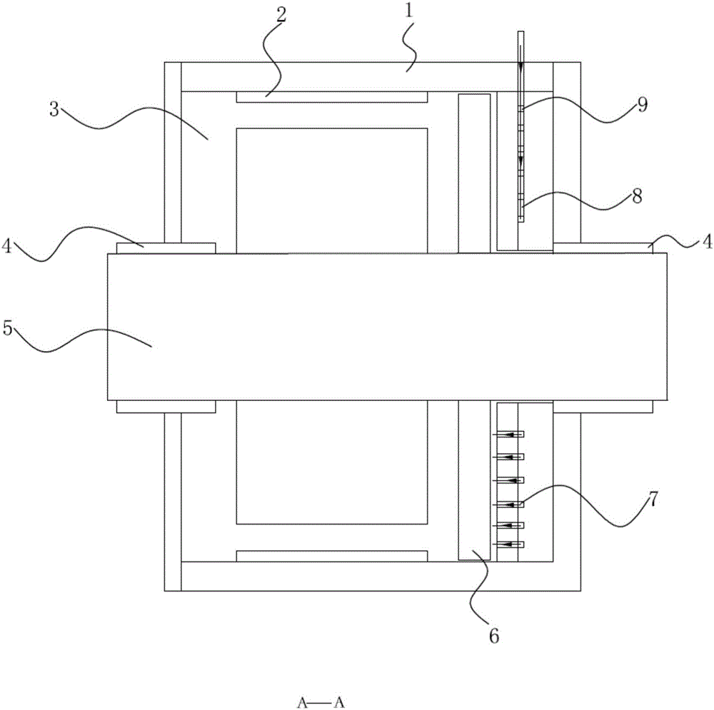
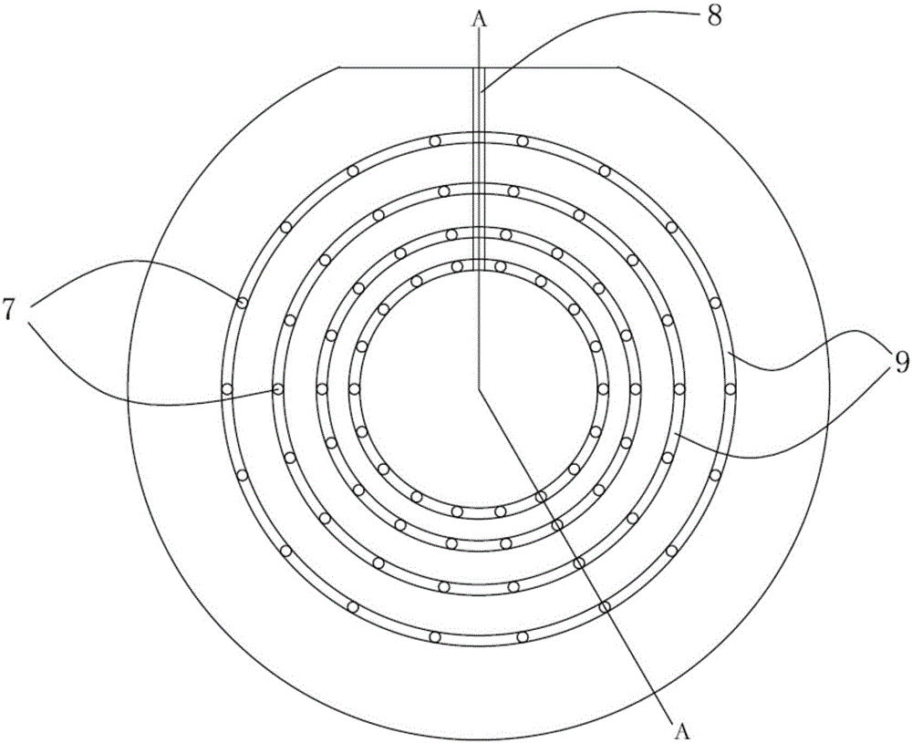
[0031] A pneumatic power generating device such as Figure 1-2 As shown, it includes a base 1, a stator 2 arranged on the base 1, a rotor 5 matched with the stator 2, a driving wheel 6 is arranged on the rotor 5, and the end surface of the driving wheel 6 is A drive hole for driving the drive wheel 6 to rotate is provided, the rotor 5 is set in the revolving cavity 3 of the base 1 through the air bearing 4, the base 1 is provided with an air passage, and the The air channel includes an air flotation air channel acting on the air flotation support 4, and a driving air channel acting on the driving hole, the rotor 5 shares the same air source with the air flotation support 4, and the air flotation The floating air channel communicates with the driving air channel through the rotary cavity 3 .
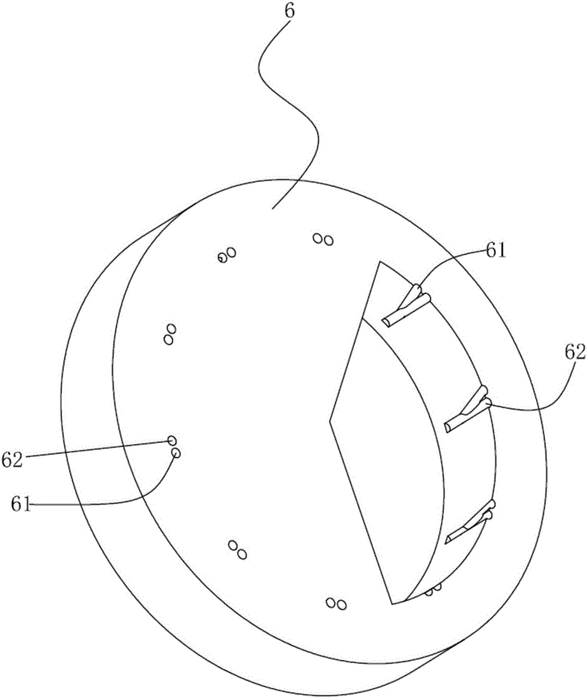
[0032] More specifically, such as image 3 As shown, the drive hole includes an exhaust hole 62 and an inclined counterbore 61, the exhaust hole 62 communicates with the inclined counte...
Embodiment 2
[0038]A pneumatic power generating device such as Figure 1-2 As shown, it includes a base 1, a stator 2 arranged on the base 1, a rotor 5 matched with the stator 2, a driving wheel 6 is arranged on the rotor 5, and the end surface of the driving wheel 6 is A drive hole for driving the drive wheel 6 to rotate is provided, the rotor 5 is set in the revolving cavity 3 of the base 1 through the air bearing 4, the base 1 is provided with an air passage, and the The air channel includes an air flotation air channel acting on the air flotation support 4, and a driving air channel acting on the driving hole, the rotor 5 shares the same air source with the air flotation support 4, and the air flotation The floating air channel communicates with the driving air channel through the rotary cavity 3 .
[0039] More specifically, such as Figure 4 As shown, the drive hole includes an exhaust hole 62 and an inclined counterbore 61, the exhaust hole 62 communicates with the inclined counte...
Embodiment 3
[0045] A pneumatic power generating device such as Figure 1-2 As shown, it includes a base 1, a stator 2 arranged on the base 1, a rotor 5 matched with the stator 2, a driving wheel 6 is arranged on the rotor 5, and the end surface of the driving wheel 6 is A drive hole for driving the drive wheel 6 to rotate is provided, the rotor 5 is set in the revolving cavity 3 of the base 1 through the air bearing 4, the base 1 is provided with an air passage, and the The air channel includes an air flotation air channel acting on the air flotation support 4, and a driving air channel acting on the driving hole, the rotor 5 shares the same air source with the air flotation support 4, and the air flotation The floating air channel communicates with the driving air channel through the rotary cavity 3 .
[0046] More specifically, such as Figure 5 As shown, the drive hole includes an exhaust hole 62 and an inclined counterbore 61, the exhaust hole 62 communicates with the inclined count...
PUM
 Abstract
Description
Claims
Application Information
 - R&D
- Intellectual Property
- Life Sciences
- Materials
- Tech Scout
- Unparalleled Data Quality
- Higher Quality Content
- 60% Fewer Hallucinations
Browse by: Latest US Patents, China's latest patents, Technical Efficacy Thesaurus, Application Domain, Technology Topic, Popular Technical Reports.
© 2025 PatSnap. All rights reserved.Legal|Privacy policy|Modern Slavery Act Transparency Statement|Sitemap|About US| Contact US: help@patsnap.com