
Filterelement

一种过滤件、过滤介质的技术,应用在过滤分离、膜过滤器、固定式滤芯过滤器等方向,能够解决过滤件安装困难、安装空间限制、复杂几何形状等问题,达到低材料成本、低劳动成本、大有效过滤面积的效果

Inactive Publication Date: 2016-09-28
MANN HUMMEL GMBH
View PDF7 Cites 2 Cited by
  • Summary
  • Abstract
  • Description
  • Claims
  • Application Information

AI Technical Summary

Problems solved by technology

In practice, however, the installation space available for the filter element is often very limited, especially in motor vehicles, and also has complex geometries, especially because of other components
The installation of the aforementioned filter elements thus often becomes difficult

Method used


Image

  • Filterelement
  • Filterelement
  • Filterelement

Examples


Embodiment Construction

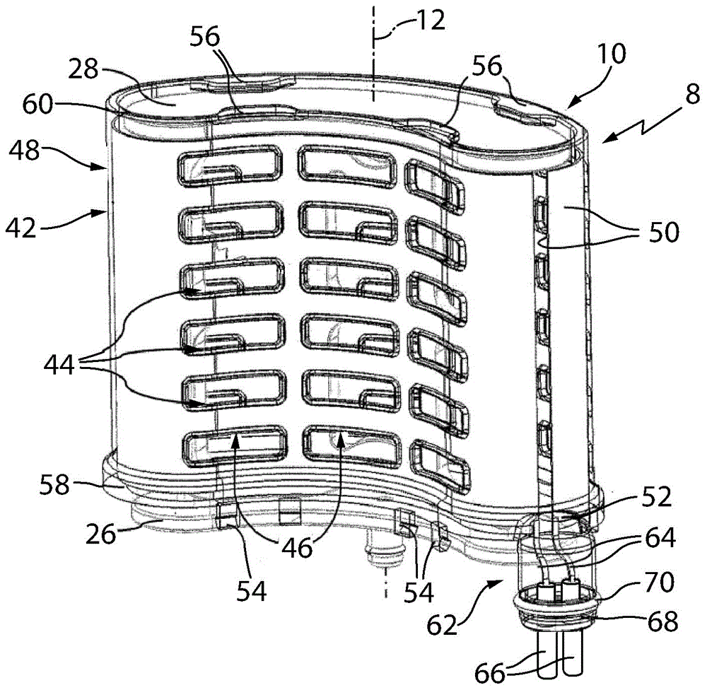
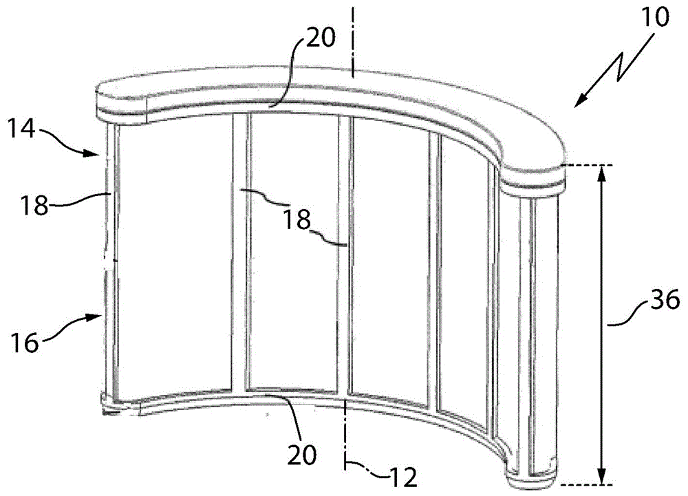
[0037] figure 1A filter element 10 for filtering fluid containing impurities is shown. The filter element 10 here has, for example, an essentially kidney-shaped or banana-shaped basic shape with a longitudinal axis 12 . The filter element 10 can also have another shape, if this requires the geometry of the respective installation space of the filter element 10 . The filter element 10 has at least one filter medium 14 . filter media 14 in figure 1 are reproduced transparently for illustration purposes. Figure 8 An alternative view of the filter element 10 is shown. The filter medium 14 is supported on the inside of a support 16 in the form of a grid plate and is arranged annularly around the support 16 .

[0038] The support element 16 has a curved or curved width extension, which is due to the desired basic shape of the filter element 10 . The longitudinal and transverse bars of the support 16 are indicated with 18 or 20 . The longitudinal and transverse webs define a ...


PUM


Abstract

The invention relates to a filter element for a fluid. The filter element for a fluid includes: an elongated grid-type supporting element; a filter medium supported on the supporting element; wherein the support element and filter medium is configured such that the fluid flows through the filter medium in a direction radially to a longitudinal axis of the filter element; wherein the supporting element is a grid plate and / or the filter medium is embedded in the material of the supporting element at least in some sections.

Description

technical field [0001] The invention relates to a filter element for filtering fluid and a filter element assembly having such a filter element. Background technique [0002] Filter elements are used in practice to separate the impurities contained in the fluid from the fluid. The filter element generally has an elongated grid-like support. A filter medium is supported on the support element, through which a fluid can flow radially relative to the longitudinal axis of the filter element. [0003] Such filter elements are used, for example, to filter fuel (diesel) or also to filter urea solutions, which are used for the reduction of nitrogen oxides in the exhaust gases of internal combustion engines of motor vehicles. In practice, however, the installation space available for the filter element is usually very limited, especially in motor vehicles, and also has a complex geometry, especially because of other components. Mounting of the aforementioned filter element is thus...

Claims


Application Information

Patent Timeline
Patent Type & Authority Applications(China)
IPC IPC(8): F01N3/20F01N3/28F02M37/22
CPCF02M37/30F01N3/2013F01N3/28F01N2610/02F01N2610/1426B01D35/18B01D2201/296B01D2201/305B01D2201/60B01D29/15
Inventor H.维勒C.奥普里施J.贝雷尔T.弗里德里希P.托法尔
Owner MANN HUMMEL GMBH
Learn More