Rotary shaft automatic locking mechanism

An automatic locking and rotating shaft technology, applied in the direction of brake actuators, gear transmission mechanisms, mechanical equipment, etc., can solve the problems of incomplete electromagnetic screen, unreliable unlocking of the locking mechanism, and large space occupied by the locking mechanism. Achieve good application value and promotion prospects, convenient and quick locking and unlocking conversion, and solve the effect of poor work reliability

Active Publication Date: 2018-04-06
HUBEI SANJIANG AEROSPACE WANFENG TECH DEV
View PDF6 Cites 0 Cited by
  • Summary
  • Abstract
  • Description
  • Claims
  • Application Information

AI Technical Summary

Problems solved by technology

[0003] At present, the commonly used locking mechanisms in China include bolt-type, shaft-holding, and end-toothed-disk locking mechanisms. These methods have certain advantages and disadvantages during use. The bolt-type locking mechanism is mainly driven by a motor. The spring pin is accurately inserted into the locking hole of the rotating part. The advantage of this mechanism is that the locking is reliable. The disadvantage is that the entire locking mechanism takes up a lot of space, the control system is complicated, and the cost is high.
Shaft-holding locking mainly uses the structural principle of the brake pad to hold the shaft tightly, and controls the opening or locking of the brake pad through the pulling force of the motor. The advantage of this mechanism is that it occupies a small space and is easy to install and adjust. The disadvantage is that the entire mechanism The reliability of the locking performance is poor, and the locking wire rope needs to be adjusted regularly, and the use of push protection is more cumbersome
The end-toothed locking mechanism is mainly to process a pair of high-precision toothed plates, which are respectively installed on the end face of the rotary shaft and the end face of the locking mechanism, and are locked by intermeshing gears. The advantage of this mechanism is the stability after locking Better, high reliability, the disadvantage is high cost, the whole mechanism occupies a large axial space
[0004] The most important problems in the use of commonly used locking mechanisms such as bolt type, shaft holding type, and end sprocket type are: high reliability in short-term use, such as long-term use after long-term storage or vibration, shock, high and low temperature When used again, the reliability will be greatly reduced
This type of mechanism basically uses the thread pair in the locking mechanism to move, and relies on the thread pair in the mechanism to lock itself when locking. Since the thread pair installed in the locking mechanism is under stress for a long time, it has not worked for a period of time. Finally, due to temperature difference, transportation vibration and other reasons, the thread pair in the mechanism will produce a certain elastic or plastic deformation. When unlocking, it is necessary to overcome this thread deformation first, which will increase the initial unlocking force more, resulting in the locking mechanism unlocking. Reliable phenomenon, even unusable
[0005] There is also an electromagnetic clutch locking mechanism, which mainly uses the principle of electromagnetic clutch to install an electromagnetic clutch between the rotating shaft and the base, and achieves locking or unlocking by turning on and off the entire electromagnetic clutch locking mechanism. Purpose, the advantages of this mechanism are reliable locking, simple structure, and small space occupation. The disadvantage is that the electromagnetic field generated by the whole mechanism is large, which has large electromagnetic interference to the equipment and has a large impact on the surrounding electronic equipment. The influence of this kind of locking mechanism can not completely carry out electromagnetic shielding at the same time

Method used


Image

  • Rotary shaft automatic locking mechanism
  • Rotary shaft automatic locking mechanism
  • Rotary shaft automatic locking mechanism

Examples


Embodiment Construction

[0019] Below in conjunction with accompanying drawing and specific embodiment the present invention is described in further detail:

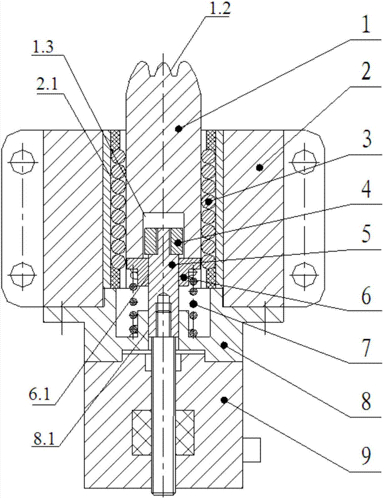
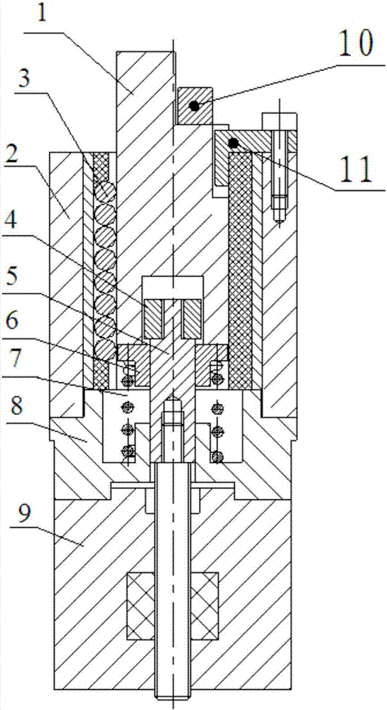
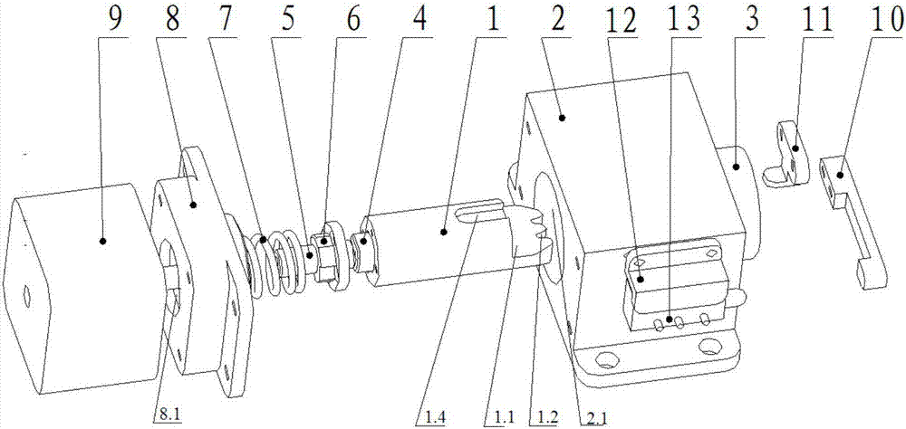
[0020] Such as Figure 1~6 The automatic locking mechanism of the rotating shaft shown includes a toothed cylindrical slider 1 (the diameter of the outer circle is 20mm), a locking bracket 2, a linear bearing 3 (model LM20UU), a limit nut 4, a guide stud 5, a push Rod seat 6, spring 7, motor mounting seat 8, linear motor 9 (type 43000 linear stepper motor), potentiometer sensing sheet 10, potentiometer pressing plate 12 and potentiometer 13, wherein the inside of the locking bracket 2 A cylindrical hole 2.1 is provided at the middle position, and the toothed cylindrical slider 1 is set in the cylindrical hole 2.1 through a linear bearing 3. The front end of the toothed cylindrical slider 1 is provided with a notch 1.1, and a potentiometer sensing piece 10 is installed on the notch 1.1. The front end of the toothed cylindrical slider 1 is provid...


PUM


Abstract

The invention discloses an automatic locking mechanism of a rotary shaft. A cylindrical hole is formed in a locking support. A toothed cylinder sliding block is arranged in the cylindrical hole through a linear bearing. A notch is formed in the front end of the toothed cylinder sliding block, and a potentiometer induction sheet is arranged in the notch. A sliding groove is formed in the rear end of the toothed cylinder sliding block. A limiting nut is arranged in the sliding groove. A base body of a push rod base is fixed to the rear end of the toothed cylinder sliding block. A guide through hole is formed in the push rod base. The front end of a guide stud penetrates through the guide through hole and is in threaded connection with the limiting nut. A linear motor is fixedly connected with the rear end of the locking support through a motor mounting base. A power output shaft of the linear motor is fixedly connected with the guide stud in a coupling hole. One end of a spring is connected with the base body of the push rod body, and the other end of the spring is connected with the positioning face of the motor mounting base. A potentiometer is fixed to the locking support, the potentiometer induction sheet is connected with the induction end of the potentiometer, and the control signal output end of the potentiometer is connected with a control signal input end of the linear motor. The automatic locking mechanism of the rotary shaft is high in environmental adaptability and compact in structure.

Description

technical field [0001] The invention relates to the technical field of mechanical manufacturing, in particular to an automatic locking mechanism for a rotating shaft. technical background [0002] In many automatic rotary devices such as automatic turntables, automatic rotary frames or automatic rotary measuring instruments produced in China, whether it is indoor equipment or vehicle-mounted equipment, in order to control the working state of the internal shaft, an automatic locking mechanism must be installed inside the equipment. During testing or use, the rotating shaft must be automatically locked to meet the needs of automated processes in the working process. [0003] At present, the commonly used locking mechanisms in China include bolt-type, shaft-holding, and end-toothed-disk locking mechanisms. These methods have certain advantages and disadvantages during use. The bolt-type locking mechanism is mainly driven by a motor. The spring pin is accurately inserted into ...

Claims


Application Information

Patent Timeline
Patent Type & Authority Patents(China)
IPC IPC(8): F16D49/00F16D65/14F16D121/24
CPCF16D49/00F16D65/14F16D2121/24
Inventor 李海峰牟方佳杨道安王亚军刘群昌马柯张书文
Owner HUBEI SANJIANG AEROSPACE WANFENG TECH DEV
Why Eureka
Try Eureka