Rotation type waterway three-way switching device

A switching device, rotary technology, applied in valve devices, multi-port valves, engine components, etc., can solve the problems of small total water output, reduce water flow velocity, increase water flow resistance, etc., to achieve higher adjustment sensitivity and reduce flow. Resistance, the effect of increasing water output

Active Publication Date: 2016-09-28
浙江豪路热能科技有限公司
View PDF6 Cites 4 Cited by
  • Summary
  • Abstract
  • Description
  • Claims
  • Application Information

AI Technical Summary

Problems solved by technology

The waterway groove between the second water inlet pipe and the second communication hole in the above technical content is U-shaped, the waterway is long, and the structure of multiple chambers increases the flow resistance of the water flow, and the total water output is small. The adjustment sensitivity of the operation is low, the sealing is poor, etc.
[0005] At the same time, when the traditional valve core selectively connects to the water inlet port, the water flow needs to be squeezed out from the gap between the valve core and the valve seat cavity to the water outlet after flowing out of the water inlet port, which greatly reduces the flow rate of the water flow. , so that the water outlet effect of the switching device is not good

Method used


Image

  • Rotation type waterway three-way switching device
  • Rotation type waterway three-way switching device
  • Rotation type waterway three-way switching device

Examples


Embodiment 1

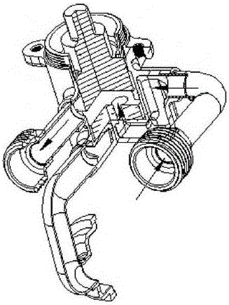
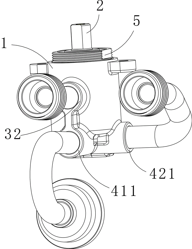
[0031] Embodiment 1, the valve body 1 is integrally formed by a forging process, wherein the water inlet channel includes a first water inlet channel 41 and a second water inlet channel 42, both of which are straight channels . The first water inlet channel 41 includes a first water inlet port 411 and a first water outlet port 412 , and the second water inlet channel 42 includes a second water inlet port 421 and a second water outlet port 422 . The first water inlet port 411 of the first water inlet channel 41 is located directly below the water outlet 32 ​​, and the first water inlet port 411 is at a right angle to the second water inlet port 421 of the second water inlet channel 42 .

[0032] When the switching mechanism 2 is placed in the valve body 1, it can be rotated so that a passage is formed between the first water inlet port 411, the first water outlet port 412 and the water outlet 32, and at the same time the second water inlet channel 42 is closed; or the second wa...

Embodiment 2

[0033] Embodiment 2, in order to reduce the flow resistance of water flow, both the first water inlet channel 41 and the second water inlet channel 42 are L-shaped channels, wherein the transverse diameter of the first water inlet channel 41 is the same as that of the second water inlet channel 42 The transverse diameters are the same, and the longitudinal diameter of the first water inlet channel 41 is the same as that of the second water inlet channel 42 .

[0034] Meanwhile, the first water inlet port 411 and the second water inlet port 421 are located at the same level. Others are the same as in Embodiment 1.

Embodiment 3

[0035] Embodiment 3, in order to solve the problem that the water needs to be squeezed out of the valve body, the switching mechanism 2 includes a housing 21, a rotating shaft 22, a locking member 23 and a bottom plate 24. The top of the housing 21 is provided with a through hole 211, and the housing 21 A plurality of windows 212 are defined on the side wall, and the rotating shaft 22 is inserted into the through hole 211 of the housing 21 to be rotatably connected with the housing 21 . The lower part of the rotating shaft 22 is connected with a locking piece 23 and a bottom plate 24 , both of which are placed in the casing 21 , and the bottom plate 24 is close to the bottom surface of the water outlet area 3 of the valve body 1 . Wherein, there is a gap between the bottom plate 24 and the locking member 23 .

[0036] The bottom plate 24 is provided with a circular notch 241 matching the diameter of the water outlet port. The bottom plate 24 can make the circular notch 241 be lo...


PUM


Abstract

The invention belongs to the technical field of control devices for waterways of electric water heaters, and particularly relates to a rotation type waterway three-way switching device which comprises a valve body and a rotatable switching mechanism. The valve body can be connected with a water inlet / outlet pipe, and comprises a water outlet area and a water inlet area. An air outlet, which can be connected with a water outlet pipe, is formed in the side wall of the water outlet area. Water inlet passages are arranged in the water inlet area, and comprise water inlet end ports and water outlet end ports. The water inlet end ports are formed in the side wall of the water inlet area. The water outlet end ports communicate with the cavity of the water outlet area. The water inlet passages comprise a first water inlet passage and a second water inlet passage. The first water inlet end port of the first water inlet passage is formed under the water outlet. A right angle is formed between the first water inlet end port and the second water inlet end port of the second water inlet passage. The first water inlet passage and the second water inlet passage are straight passages. The rotation type waterway three-way switching device, provided by the invention, is simple in structure, smooth in water flow, and high in sealing performance.

Description

technical field [0001] The invention belongs to the technical field of waterway control devices for electric water heaters, and in particular relates to a rotary waterway tee switching device. technical background [0002] According to the water needs of households and offices, there are many waterway switching devices suitable for water heaters. When multiple water heaters are installed in the same use environment, the waterway switching device can switch to use electric water heaters, gas water heaters, solar water heaters, etc. One of the hot water can be selected by the user according to the season or functional needs. However, most of the commercially available waterway switching devices have many problems such as poor waterway sealing, complicated manufacturing process, and high production cost. [0003] Most of the prior art adopts the technical content disclosed in the Chinese patent CN203488785U: the manual waterway switching device includes a valve seat with a fir...

Claims


Application Information

Patent Timeline
Patent Type & Authority Applications(China)
IPC IPC(8): F16K11/085
CPCF16K11/085
Inventor 陈雪峰陈龙郑奇龙
Owner 浙江豪路热能科技有限公司
Why Eureka
Try Eureka