Main piston rod, air control valve and lubricating method for slide valve pair

A main piston rod and air control technology, applied in the direction of engine lubrication, valve operation/release device, valve details, etc., can solve problems such as poor lubrication of slide valve pairs

Active Publication Date: 2016-09-28
成都海瑞斯轨道交通设备有限公司
View PDF7 Cites 6 Cited by
  • Summary
  • Abstract
  • Description
  • Claims
  • Application Information

AI Technical Summary

Problems solved by technology

[0004] The present invention provides a method for lubricating the main piston rod, the air control valve and the slide valve pair, which i

Method used


Image

  • Main piston rod, air control valve and lubricating method for slide valve pair
  • Main piston rod, air control valve and lubricating method for slide valve pair

Examples


Embodiment 1

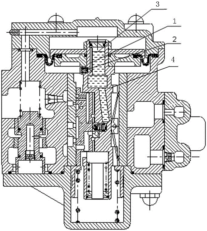
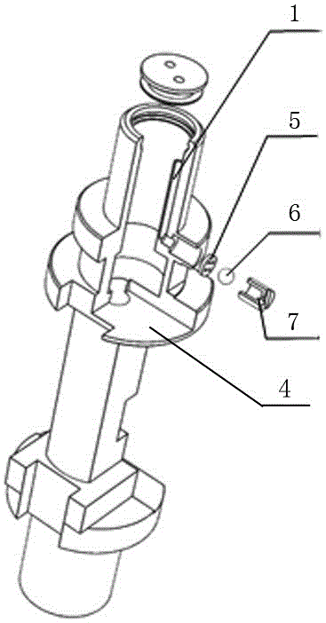
[0043] like figure 1 and figure 2 As shown, a main piston rod includes a main piston rod body 4, an oil storage chamber 3 is arranged on the main piston rod body 4, and a balance valve 2 and a balance pipe 1 are also included;

[0044] The balance valve 2 includes a valve seat 7 and a sliding body 6, the valve seat 7 is cylindrical, the sliding body 6 is located in the hollow area of ​​the valve seat 7, and the sliding body 6 can move along the length of the valve seat 7 direction movement;

[0045] Both ends of the valve seat 7 are provided with sealing plates, the two sealing plates are respectively the sealing plate A5 and the sealing plate B, and the two sealing plates are all provided with through holes for the fluid to enter and exit the hollow area, and the sliding body 6 is in the When moving to contact with the sealing plate A5, the sliding body 6 does not affect the medium flow capacity of the through hole on the sealing plate A5, and when the sliding body 6 moves...

Embodiment 2

[0053] like figure 1 and figure 2 As shown, this embodiment is further limited on the basis of Embodiment 1: a circular blind hole is provided on the outside of the main piston rod body 4, an internal thread is provided on the circular blind hole, and the valve seat 7 To be provided with a cylinder with external threads, the sealing plate A5 is in the shape of a disc, and a plurality of through holes are arranged on the sealing plate A5, and the valve seat 7 is threadedly connected with the circular blind hole, and the sealing plate A5 is penetrated into the circle by the valve seat 7. One end of the shaped blind hole is pressed on the bottom of the circular blind hole, the sealing plate B is disc-shaped, the through hole on the sealing plate B is located at the center of the sealing plate B, and the sealing plate B is fixed on the end of the valve seat 7;

[0054] The balance pipe 1 is a hole provided on the main piston rod body 4, and one end of the hole is located on the ...

Embodiment 3

[0065] This embodiment further defines this case on the basis of any one of the technical solutions provided by any one of the above embodiments, such as figure 1 and figure 2 As shown, this embodiment also discloses an air control valve, the air control valve includes a control valve body, a slide valve sleeve fixed on the control valve body, a slide valve that forms a slide valve pair with the slide valve sleeve, The throttle valve matched with the spool valve also includes the main piston rod provided by any of the above schemes, the main piston rod is used to drive the spool valve to slide, the through hole on the sealing plate B on the balance valve 2 and the spool valve chamber The air cavity is connected. Since the air control valve adopts the main piston rod provided above, the balance valve 2 on the main piston rod produces a lubrication method different from that of the prior art, which not only enables the slide valve pair of the air control valve to be forced to ...


PUM


Abstract

The invention discloses a main piston rod, an air control valve and a lubricating method for a slide valve pair. Compared with the prior art, a balance valve and a balance pipe are arranged on a main piston rod body, the upper end of the balance pipe is located above the lubricating oil liquid level, and the lower end of the balance pipe is communicated with a slide valve chamber through the balance valve. Accordingly, lubricating oil stored in a main piston can be delivered to all lubricating points, in the low pressure state or zero pressure state, caused by emergency braking or long-time vehicle stopping or air braking value storing and transporting after a test is completed, of the slide valve chamber, the pressure in an oil storage cavity is discharged in a delayed mode to achieve balance with that in the slide valve chamber, therefore, the problem that a large amount of the lubricating oil is drained through the lubricating points to cause the stored oil to be exhausted in a short time due to the fact that the pressure in the oil storage cavity is kept high and the pressure in the slide valve chamber is low or zero, and particularly on the condition that the plane of the slide valve pair is damaged is avoided, and then long-time continuous lubricating is achieved.

Description

technical field [0001] The invention relates to the technical field of valve body structure, in particular to a lubrication method for a main piston rod, an air control valve and a sliding valve pair. Background technique [0002] In the existing air control valves represented by 120 valves, the key control mechanism of the spool valve pair is damaged in the working surface due to the failure of long-term continuous lubrication due to lubrication, which affects performance stability. It is also one of the important reasons for the short maintenance period of the air control valve. [0003] For the lubrication scheme of the spool valve pair in the air control valve, it is necessary for those skilled in the art to do further research to improve the lubrication condition of the spool valve pair. Contents of the invention [0004] The present invention provides a lubricating method for the main piston rod, the air control valve and the slide valve pair, which is used to solve...

Claims


Application Information

Patent Timeline
IPC IPC(8): F16K31/122F16N1/00
CPCF16K31/122F16N1/00
Inventor 罗长秀王鸿飞
Owner 成都海瑞斯轨道交通设备有限公司
Why Eureka
Try Eureka