
Ground penetrating radar underground horizon detection method

A technology of ground penetrating radar and detection method, applied in the field of radar system, can solve the problems of low tracking accuracy of event axis, misidentification of adjacent horizons, slow interpretation speed, etc., to achieve the effect of fast and effective extraction

Active Publication Date: 2016-09-28
INST OF ELECTRONICS CHINESE ACAD OF SCI
View PDF5 Cites 13 Cited by
  • Summary
  • Abstract
  • Description
  • Claims
  • Application Information

AI Technical Summary

Problems solved by technology

This tracking method is suitable for any complex ground-penetrating radar data. Its main advantage is that it fully utilizes the experience of data interpreters. It can overcome the shortcomings of non-artificial methods when the signal-to-noise ratio is low. The shortcoming lies in the interpretation speed. Slow, the accuracy of event tracking is not high, there are weak jumps, etc.
[0010] (1) The actual underground layered structure is not completely continuous, and the premise of the horizon correlation detection method is to assume that the reflection layer is continuous, so once encountering a horizon interruption or anomaly, the algorithm will not stop immediately, but Continue to detect according to the false horizon, which will easily cause the detection result to deviate from its actual position
[0011] (2) When there are two or more layers in the ground very close to each other, the layer correlation detection method may mistake the adjacent layers for the detected layer

Method used


Image

  • Ground penetrating radar underground horizon detection method
  • Ground penetrating radar underground horizon detection method
  • Ground penetrating radar underground horizon detection method

Examples


Embodiment Construction

[0048]In order to make the object, technical solution and advantages of the present invention clearer, the present invention will be further described in detail below in conjunction with specific embodiments and with reference to the accompanying drawings. The following description of the embodiments of the present invention with reference to the accompanying drawings is intended to explain the general inventive concept of the present invention, but should not be construed as a limitation of the present invention.

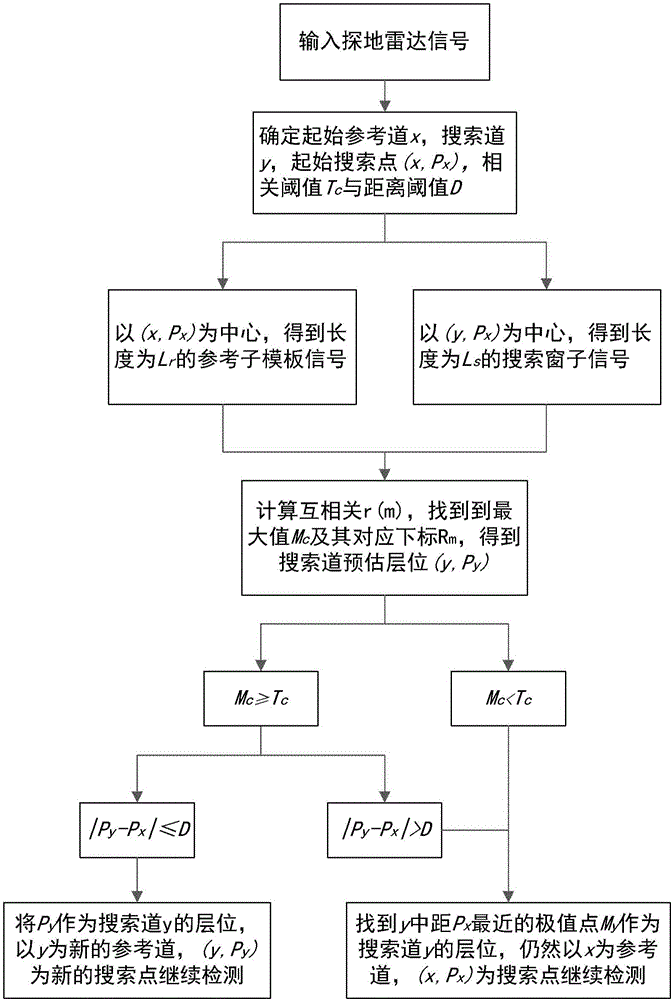
[0049] According to the general inventive concept of the present invention, a ground penetrating radar underground layer detection method is provided, comprising the following steps:

[0050] S1: Input the echo signal of ground penetrating radar;

[0051] S2: Determine the initial reference trace and initial search point from the echo signal, determine the search trace, and determine the correlation threshold T c and the distance threshold D, and determine the siz...


PUM


Abstract

he invention relates to a ground penetrating radar underground horizon detection method. The method comprises steps that S1, a ground penetrating radar echo signal is inputted; S2, an initial reference track and an initial search point are determined through the echo signal, a search track is determined, a relevant threshold Tc and a distance threshold D are determined, and sizes of a reference window and a search window are determined; S3, a cross-correlation value r(m) of a signal in the reference race reference window and a signal in a next signal search track window is calculated; S4, a search track horizon, a next reference track and a next signal search track are determined according to the calculation result and the set thresholds Tc and D; and S5, horizon detection is carried out through iteration of the steps S3-S4. According to the method, on the basis of correlation and continuity among ground penetrating radar signals, rapid effective extraction of the underground horizon information of the ground penetrating radar signals is realized, and great importance to ground penetrating radar data interpretation and geological analysis in engineering applications is realized.

Description

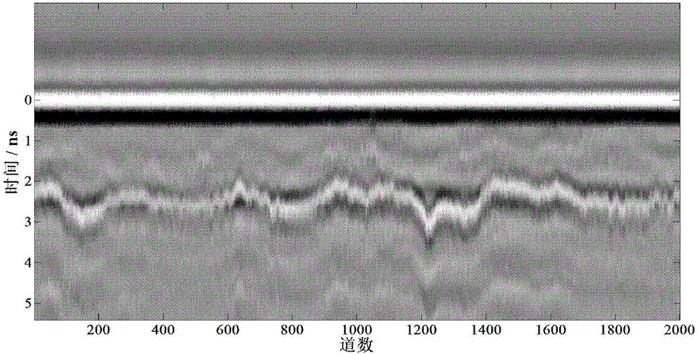
technical field [0001] The invention relates to a radar system, and further relates to a ground-penetrating radar underground layer detection method. Background technique [0002] The geological interpretation of ground penetrating radar data is the purpose of ground penetrating radar measurement. This work is usually in the radar data profile obtained after data processing, according to the waveform and intensity characteristics of the reflected wave, through the tracking of the phase axis, to determine the ground penetrating radar According to the geological meaning of the signal, the final result map of the entire survey area is obtained according to the interpretation of the section diagram. As long as there is an electrical difference in the underground medium, the corresponding reflected wave can be found in the radar image section. Therefore, the basis of GPR geological interpretation is to extract the underground reflective layer. [0003] The signs to identify refl...

Claims


Application Information

Patent Timeline
IPC IPC(8): G01S13/88G01V3/12
CPCG01S13/885G01V3/12
Inventor 刘小军董泽华叶盛波方广有张晓娟
Owner INST OF ELECTRONICS CHINESE ACAD OF SCI
Learn More