Spaceborne sliding bunching MIMO-SAR imaging method based on multi-frequency subband concurrency

A technology of MIMO-SAR and imaging method, applied in the field of spaceborne sliding spotlight MIMO-SAR imaging

Active Publication Date: 2016-09-28
HEFEI UNIV OF TECH
View PDF4 Cites 8 Cited by
  • Summary
  • Abstract
  • Description
  • Claims
  • Application Information

AI Technical Summary

Problems solved by technology

However, existing literature only discusses multi-frequency sub-band concurrent MIMO-SAR in strip mode

Method used


Image

  • Spaceborne sliding bunching MIMO-SAR imaging method based on multi-frequency subband concurrency
  • Spaceborne sliding bunching MIMO-SAR imaging method based on multi-frequency subband concurrency
  • Spaceborne sliding bunching MIMO-SAR imaging method based on multi-frequency subband concurrency

Examples


Embodiment Construction

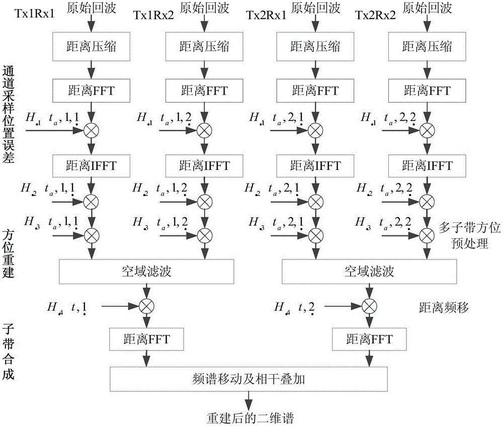
[0047] Such as figure 1 As shown, the space-borne sliding spotlight MIMO-SAR imaging method based on multi-frequency sub-band concurrent includes the following steps:

[0048] Step 1: Receive the original SAR echo signal with a full aperture in the channel mode of one transmission and multiple reception, and perform azimuth bandwidth compression processing and beam compression processing on the echo signal to obtain the echo signal:

[0049] s 1 ( t , t a , n , m ) = S 1 ( t , t a + Δt n m , f n ) ...


PUM


Abstract

The invention discloses a spaceborne sliding bunching MIMO-SAR imaging method based on multi-frequency subband concurrency. The difficulty and the cost of a radar system are reduced, and at the same time two-dimensional high resolution, wide mapping band and high signal to noise ratio are acquired. According to the realizing process, a channel sampling position error correction method is proposed; a multi-subband orientation de-skewing method is proposed; the Doppler bandwidth of a signal is reduced to be less than the equivalent PRF of a system; after orientation de-skewing, the distance course difference among subband signals can be easily compensated; and a traditional frequency-domain subband splicing method is improved, so that the method avoids distance-to-interpolation, has no special requirements on system parameters, and has higher adaptability.

Description

technical field [0001] The invention relates to the field of radar imaging methods, in particular to a multi-frequency sub-band concurrent spaceborne sliding spotlight MIMO-SAR imaging method. Background technique [0002] Resolution and swath are the two most important performance indicators of spaceborne SAR, but due to the limitation of the minimum antenna area, they constitute a pair of contradictions. To solve this problem, scholars at home and abroad have proposed a variety of solutions, among which azimuth multi-channel SIMO-SAR combined with digital beamforming technology is the most widely used solution. Under the premise of ensuring the distance without ambiguity and wide swath, the scheme adopts signal processing method to suppress Doppler ambiguity, so as to realize high-resolution wide swath SAR imaging. In order to meet the various requirements of SAR applications for resolution and swath, azimuth multi-channel SIMO-SAR has been extended from the original stri...

Claims


Application Information

Patent Timeline
Patent Type & Authority Applications(China)
IPC IPC(8): G01S13/90
CPCG01S13/90G01S13/9004G01S13/904
Inventor 周芳杨学志刘留夏晶凡
Owner HEFEI UNIV OF TECH
Why Eureka
Try Eureka