
Ultrasonic positioning system based on reflection cones

A positioning system, ultrasonic technology, applied in the radio wave measurement system, sound wave re-radiation, utilization of re-radiation, etc., can solve the problems of low positioning accuracy, cost increase, node inconvenience, etc., to expand the radiation range, facilitate layout, reduce Quantity effect

Inactive Publication Date: 2016-09-28
NANJING UNIV OF POSTS & TELECOMM
View PDF6 Cites 6 Cited by
  • Summary
  • Abstract
  • Description
  • Claims
  • Application Information

AI Technical Summary

Problems solved by technology

[0002] At present, many positioning systems use GPS satellites to locate targets. Although this positioning is very convenient, its positioning accuracy is relatively low. Most of the positioning areas are located in open outdoor areas. In many cases, we need to achieve high-precision positioning of targets Positioning, which cannot be achieved by GPS
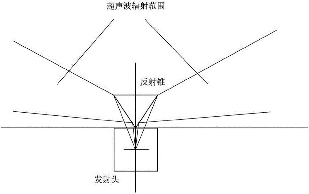
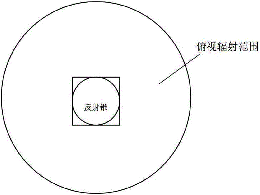
Ultrasound has good directionality, can generate reflection, refraction, and high energy on the interface. The existing ultrasonic positioning system is limited by these characteristics of ultrasonic waves. Many nodes are arranged on the ceiling, which makes the arrangement of nodes difficult. It brings inconvenience, and at the same time, due to the limitation of the launch angle of the transmitter, a large number of receiving nodes need to be arranged in a very small area, which also causes an increase in cost. In view of the node layout problem in the traditional ultrasonic positioning system, if it can Increasing the radiation range of the ultrasonic transmitting end can effectively reduce the number of receiving end nodes, thereby achieving the purpose of reducing costs

Method used


Image

  • Ultrasonic positioning system based on reflection cones
  • Ultrasonic positioning system based on reflection cones
  • Ultrasonic positioning system based on reflection cones

Examples


Embodiment Construction

[0025] Below in conjunction with accompanying drawing, technical scheme of the present invention is described in further detail:

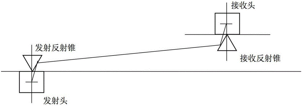
[0026] The invention discloses an ultrasonic positioning system based on a reflection cone, which includes a transmitting module, N receiving modules, a wireless communication module, a temperature sensor and a control module, where N is a natural number greater than or equal to 3;

[0027] The wireless communication module includes a summary node and N+1 branch nodes; the summary node is connected to the control module, and the N+1 branch nodes are respectively connected to the transmitting module and the N receiving modules in one-to-one correspondence; The summary node and the branch node are based on wireless communication;

[0028] The transmitting module is arranged on the object to be positioned and is used to send out ultrasonic waves, including an ultrasonic transmitter, a transmitting reflection cone and a transmitting microcontroller; th...


PUM


Abstract

The invention discloses an ultrasonic positioning system based on reflection cones. The system comprises a reflection module, N receiving modules, a wireless communication module, a temperature sensor and a control module, wherein N is a natural number greater than and equal to 3; the wireless communication module comprises one gathering node and N+1 branch nodes; the gathering node is connected with the control module, and the N+1 branch nodes are connected with the emission module and the N receiving modules in a one-to-one correspondence manner; the gathering node and the branch nodes are connected based on wireless communication; the emission module and the receiving modules each has a reflection cone added thereto; and the control module is connected with the temperature sensor for calculating coordinates of the emission module according to a temperature sensed by the temperature sensor and ultrasonic signals transmitted by each receiving module. According to the invention, the problems of inconvenient node arrangement and too many nodes in conventional ultrasonic positioning are effectively solved.

Description

technical field [0001] The invention relates to the technical field of positioning of mobile equipment, in particular to an ultrasonic positioning system based on reflection cones. Background technique [0002] At present, many positioning systems use GPS satellites to locate targets. Although this positioning is very convenient, its positioning accuracy is relatively low. Most of the positioning areas are located in open outdoor areas. In many cases, we need to achieve high-precision positioning of targets positioning, which cannot be achieved by GPS. Ultrasound has good directionality, can generate reflection, refraction, and high energy on the interface. The existing ultrasonic positioning system is limited by these characteristics of ultrasonic waves. Many nodes are arranged on the ceiling, which makes the arrangement of nodes difficult. It brings inconvenience, and at the same time, due to the limitation of the launch angle of the transmitter, a large number of receivi...

Claims


Application Information

Patent Timeline
IPC IPC(8): G01S15/06G01S7/521
CPCG01S15/06G01S7/521
Inventor 郭俊戎舟
Owner NANJING UNIV OF POSTS & TELECOMM
Learn More