Obstacle dodging method, obstacle dodging device, carrier and unmanned aerial vehicle
A carrier and obstacle avoidance technology, applied in the control field, can solve the problem of high computational complexity, achieve the effect of improving user experience, reducing computational complexity, and reducing the amount of data processed
- Summary
- Abstract
- Description
- Claims
- Application Information
AI Technical Summary
Problems solved by technology
Method used
Image
Examples
no. 1 example
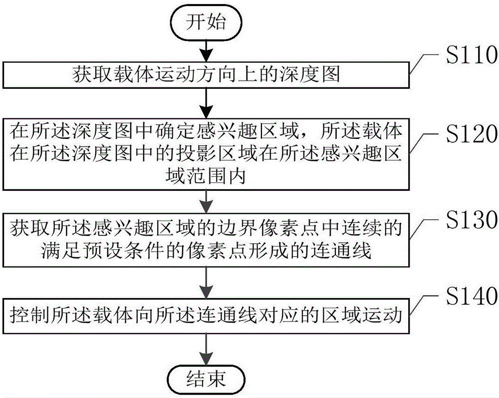
[0037] figure 2 shows the obstacle avoidance method provided by the first embodiment of the present invention, please refer to figure 2 , the method includes:
[0038] Step S110: Obtain a depth map in the moving direction of the carrier.
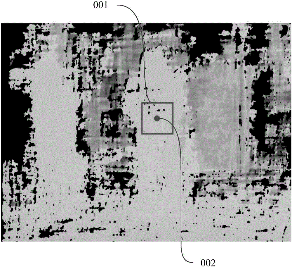
[0039] The depth map is a two-dimensional image, and the unit is a pixel point. Different pixel values of the pixel point represent different depth information, corresponding to different depth values. The depth value represents the distance between the obstacle in the depth map and the carrier. That is, different pixel values of a pixel point may represent different distances between the position in the actual environment corresponding to the pixel point and the carrier. Generally, the larger the pixel value, the farther the distance is, and the smaller the pixel value is, the closer the distance is. The correspondence between specific pixel values and distance values is determined according to actual needs, and is not limited in...
no. 2 example
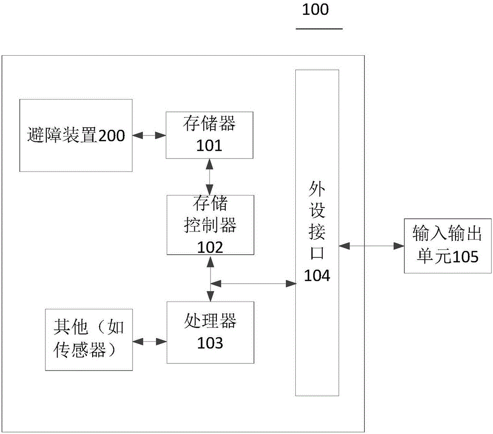
[0101] Such as Figure 9 Shown is the obstacle avoidance device 200 provided by the second embodiment of the present invention. See Figure 9 , the UAV obstacle avoidance device 200 includes:
[0102] A depth map acquisition module 210, configured to acquire a depth map in the moving direction of the carrier; a region of interest acquisition module 220, configured to determine a region of interest in the depth map, and the projection area of the carrier in the depth map is Within the scope of the region of interest; connected line acquisition module 230, used to obtain connected lines formed by continuous pixels satisfying preset conditions in the border pixels of the region of interest; motion control module 240, used to control the The carrier moves to the area corresponding to the connecting line.
[0103] Further, in this embodiment, in order to ensure that the carrier can smoothly pass through the barrier-free communication area corresponding to the communication lin...
no. 3 example
[0115] This embodiment provides a drone 300, such as Figure 10 As shown, the UAV 300 includes an image acquisition unit 310; and a processor 320, the processor 320 is electrically connected to the image acquisition unit.
[0116] Wherein, the image acquisition unit is used to acquire a depth map in the motion direction of the drone;
[0117] The processor is used to determine the region of interest in the depth map, and the projection area of the UAV in the depth map is within the range of the region of interest; obtain the border pixels of the region of interest A connection line formed by continuous pixel points satisfying preset conditions; and, controlling the UAV to move to the area corresponding to the connection line.
[0118] It can be understood that the obstacle avoidance method provided by the embodiment of the present invention can also be implemented by the overall hardware device of the drone 300 provided by this embodiment.
[0119] The image acquiring unit...
PUM
 Abstract
Description
Claims
Application Information
 - R&D
- Intellectual Property
- Life Sciences
- Materials
- Tech Scout
- Unparalleled Data Quality
- Higher Quality Content
- 60% Fewer Hallucinations
Browse by: Latest US Patents, China's latest patents, Technical Efficacy Thesaurus, Application Domain, Technology Topic, Popular Technical Reports.
© 2025 PatSnap. All rights reserved.Legal|Privacy policy|Modern Slavery Act Transparency Statement|Sitemap|About US| Contact US: help@patsnap.com


