
Method for designing variable speed pumped storage motor with double speed regulation mechanisms

A technology of pumped storage and design methods, which can be used in computing, electrical digital data processing, special data processing applications, etc., and can solve problems such as difficulties

Active Publication Date: 2016-09-28
HARBIN UNIV OF SCI & TECH
View PDF3 Cites 3 Cited by
  • Summary
  • Abstract
  • Description
  • Claims
  • Application Information

AI Technical Summary

Problems solved by technology

However, it is very difficult to meet the needs of the construction of large-capacity pumped storage power stations with greater water head changes by only using a single rotor AC excitation method to regulate the speed of pumped storage units.

Method used


Image

  • Method for designing variable speed pumped storage motor with double speed regulation mechanisms
  • Method for designing variable speed pumped storage motor with double speed regulation mechanisms
  • Method for designing variable speed pumped storage motor with double speed regulation mechanisms

Examples


Embodiment 1

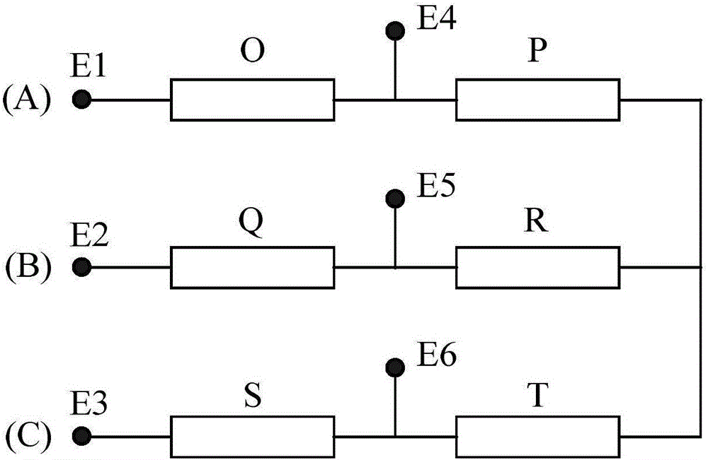
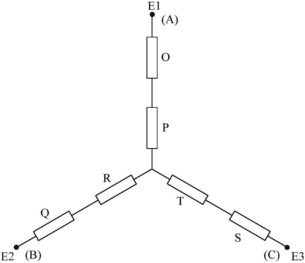
[0038] In this embodiment, the 480MV pumped storage motor is taken as an example. It is necessary to use the YY connection mode when running at high speed, and the E 1 E. 2 E. 3 ends shorted together and the E 4 E. 5 E. 6 The terminal is connected to the three-phase AC power supply; when running at low speed, the Y connection method is required, and the E 1 E. 2 E. 3 The terminal is directly connected to the three-phase AC power supply and the E 4 E. 5 E. 6 The end is suspended, the A-phase winding is divided into O-segment winding and P-segment winding, the B-phase winding is divided into Q-segment winding and R-segment winding, and the C-phase winding is divided into S-segment winding and T-segment winding.

[0039] In order to achieve two speeds of 83.33rpm and 111.1rpm for the 480MV pumped storage motor, the number of stator and rotor poles is 72 / 54, and the number of stator slots is 648. This scheme actually has 8 / 6 poles in the stator and rotor, and 9 repetitio...

Embodiment 2

[0084] In this embodiment, a 145MW pumped storage motor is taken as an example. In order to achieve two speeds of 100rpm and 120rpm, the number of stator and rotor poles is 60 / 50, and the number of stator slots is 540. This scheme actually has 12 / 10 poles in the stator and rotor, and 5 repetitions of 108 slots in the stator.

[0085] Arrange the windings of the pumped storage motor according to the pole-changing winding method, and analyze the winding factor, distribution factor, stator harmonic leakage reactance coefficient, air gap magnetic density ratio, main wave negative sequence ratio, and slot pitch after the arrangement The leakage reactance coefficient and the pitch leakage reactance coefficient at the bottom of the slot are calculated and analyzed, and the feasibility of the pole-changing winding arrangement scheme is determined. Adopt the rotor AC excitation method to adjust the speed of the pumped energy storage motor. At the position of the rotor speed of 100rpm (...


PUM


Abstract

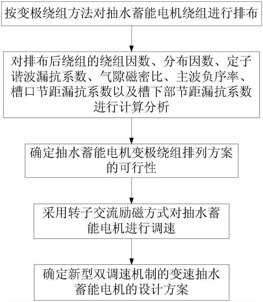
The invention provides a method for designing a variable speed pumped storage motor with double speed regulation mechanisms. The method is technically characterized by comprising the following steps that 1, pumped storage motor windings are arranged according to a change pole winding method; 2, the winding factor, distributing factor, stator harmonic leakage reactance coefficient, gap flux density ratio, dominant wave dominant wave rate, notch pitch leakage reactance coefficient and groove lower pitch leakage reactance coefficient of the arranged windings are calculated and analyzed to determine the feasibility of a pumped storage motor change pole winding arrangement scheme; 3, a rotor alternating current excitation mode is adopted for regulating the speed of the pumped storage motor; 4, the design scheme of the novel variable speed pumped storage motor controlled with double speed regulation mechanisms is determined. The change range of rotor speed of the pumped storage motor can be widened more effectively, and then the optimal operating performance of a water pump-water turbine is fully achieved.

Description

Technical field: [0001] The invention relates to the field of motor control, in particular to a design method of a variable-speed pumped energy-storage motor with a double-speed regulation mechanism. Background technique: [0002] The pumped storage motor can be made into a variable speed mode or a constant speed mode. Compared with the constant speed pumped storage unit, the variable speed pumped storage unit has more technical advantages. By changing the rotor speed, the variable speed pumped storage unit can better adapt to the two operating conditions of power generation and pumping, which improves the relationship between the pump and the turbine. The operating efficiency can also be adapted to a wider power range and head variation. At the same time, the variable-speed pumped storage unit can effectively improve the power supply quality of the power grid, significantly improve the hydraulic performance of the turbine, reduce vibration corrosion and sediment wear, and ...

Claims


Application Information

Patent Timeline
Patent Type & Authority Applications(China)
IPC IPC(8): G06F17/50
CPCG06F30/13G06F30/17
Inventor 戈宝军韩继超陶大军孙玉田黄士鹏赵洪森
Owner HARBIN UNIV OF SCI & TECH
Learn More