

Music player
A music player and vibrator technology, applied in instruments, non-electric variable control, mechanical oscillation control, etc., can solve problems such as the inability to realize slow rhythm, multi-contact vibration, and the inability of hearing-impaired people to feel music, etc.
- Summary
- Abstract
- Description
- Claims
- Application Information
AI Technical Summary
Problems solved by technology
Method used
Image

Examples
no. 1 example
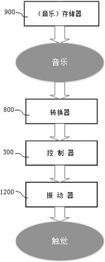
[0044] like figure 1 Shown in the working schematic diagram of the first embodiment of the present invention:
[0045] A music player 1000, at least comprising a memory 900, a converter 800, a vibrator 1200 and a controller 300;
[0046] The memory 900 stores digital files of music;
[0047] The converter 800 converts the sound wave signal in the digital file into a mechanical vibration signal;
[0048] The controller 300 controls the vibration of the vibrator 1200 according to the mechanical vibration signal;
[0049] The vibrator 1200 performs rhythmic vibration and / or strong and weak vibration according to the vibration instruction given by the controller 300 .
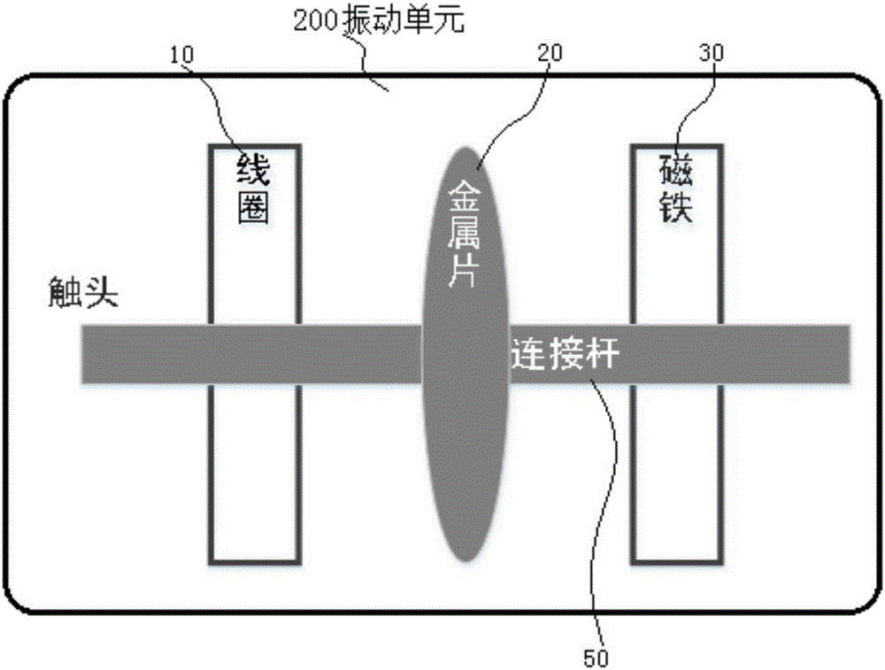
[0050] like figure 2 It is shown in the structural diagram of the vibration unit in the first embodiment of the present invention:
[0051] Preferably, in the music player 1000, the vibrator 1200 includes at least one vibration unit 200, and the vibration unit 200 includes an energized coil 10, a metal sheet ...
no. 2 example
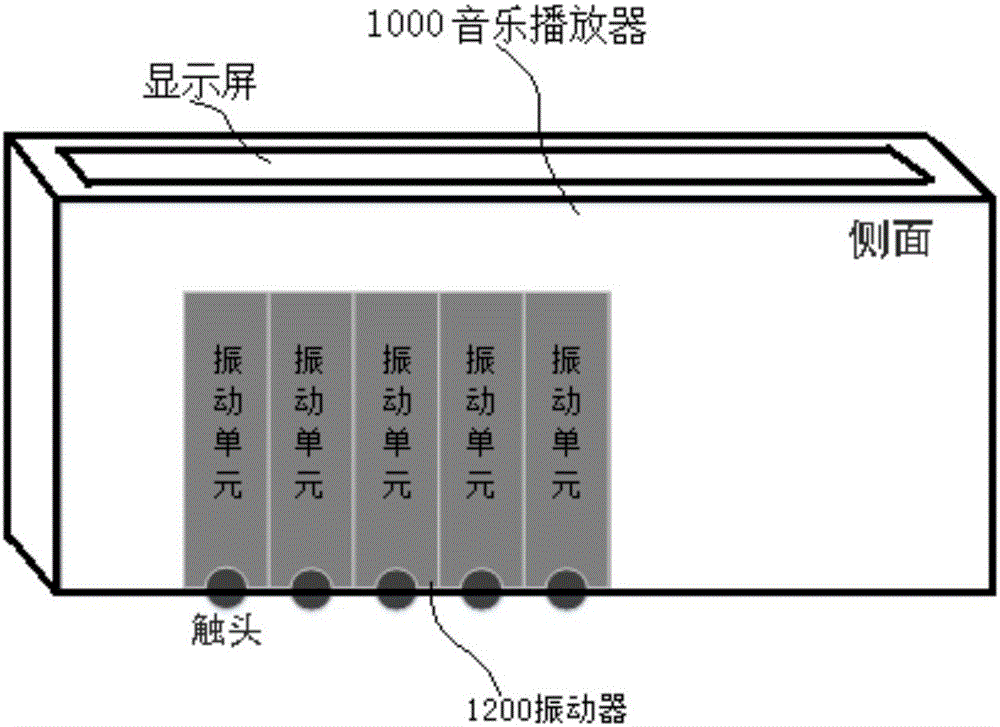
[0066] like image 3 It is a schematic diagram showing the structure of a vibrator 1200 in the second embodiment of the present invention: a plurality of vibrating units 200 are arranged into a vibrator (array) 1200 .
[0067] A music player 1000, at least comprising a memory 900, a converter 800, a vibrator 1200 and a controller 300;
[0068] The memory 900 stores digital files of music;
[0069] The converter 800 converts the sound wave signal in the digital file into a mechanical vibration signal;
[0070] The controller 300 controls the vibration of the vibrator 1200 according to the mechanical vibration signal;
[0071] The vibrator 1200 performs rhythmic vibration and / or strong and weak vibration according to the vibration instruction given by the controller 300. The vibrator 1200 includes at least one vibration unit 200, and the vibration unit 200 includes an energized coil 10. Metal sheet 20, magnet 30 and connecting rod 50;
[0072] The connecting rod 50 passes th...
no. 3 example
[0078] A music player 1000, at least comprising a memory 900, a converter 800, a vibrator 1200 and a controller 300;
[0079] The memory 900 stores digital files of music;
[0080] The converter 800 converts the sound wave signal in the digital file into a mechanical vibration signal;
[0081] The controller 300 controls the vibration of the vibrator 1200 according to the mechanical vibration signal;
[0082] The vibrator 1200 performs rhythmic vibration and / or strong and weak vibration according to the vibration instruction given by the controller 300. The vibrator 1200 includes at least one vibration unit 200, and the vibration unit 200 includes an energized coil 10. Metal sheet 20, magnet 30 and connecting rod 50;
[0083] The connecting rod 50 passes through the energizing coil 10, the metal sheet 20 and the magnet 30 in turn; the energizing coil 10 and the magnet 30 are fixedly connected to the connecting rod 50, when the energizing coil 10 is fed with current , the me...
PUM
 Abstract
Description
Claims
Application Information