A Low Noise Switched Reluctance Motor

A switched reluctance motor, low-noise technology, applied in the direction of electric components, electrical components, electromechanical devices, etc., can solve the problems of poor rotor mass balance, high noise of brushed motors, and large vibration during high-speed operation, so as not to be easily displaced , improve the connection strength, low cost effect

Active Publication Date: 2018-06-29
HUZHOU YONGCHANG BEISHITUO ELECTRIC APPLIANCE INDAL
View PDF5 Cites 0 Cited by
  • Summary
  • Abstract
  • Description
  • Claims
  • Application Information

AI Technical Summary

Problems solved by technology

[0002] At present, brush motors or brushless DC motors are used in high-speed motors such as household vacuum cleaners, hand dryers, mixers, and washing machines. The high-speed operation of the brush motor has the disadvantages of large vibration, easy detachment of magnetic tiles, and relatively high cost. The existing high-efficiency switched reluctance motor is simple but has poor rotor mass balance. It generates additional centrifugal force when it rotates, and the bearing and bracket receive periodic additional The effect of centrifugal force is transmitted to the shell through bearings and brackets to cause vibration and noise

Method used


Image

  • A Low Noise Switched Reluctance Motor
  • A Low Noise Switched Reluctance Motor
  • A Low Noise Switched Reluctance Motor

Examples


Embodiment 1

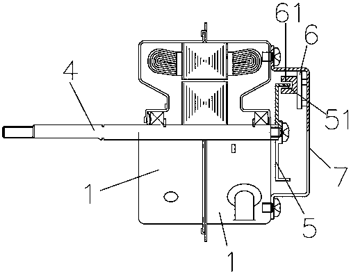
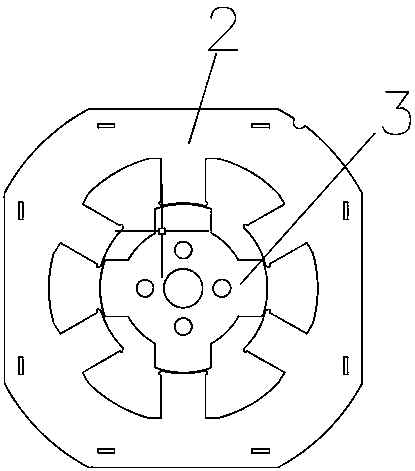
[0032] A low-noise switched reluctance motor includes an end cover 1, a stator 2 and a rotor 3 arranged in the end cover; the rotor is provided with a rotating shaft 4 connected to the end cover through a bearing, and one end of the rotating shaft protrudes from the end cover. The end cover forms an output shaft; the rotor includes a rotor body 32 and a number of teeth 31 surrounding the rotor body, and anti-vibration noise reduction blocks 81 are filled between adjacent teeth, and the anti-vibration noise reduction blocks pass through The connecting pieces located on the two end surfaces of the rotor are fixedly connected, and a reinforced engagement structure is arranged between the rotor and the anti-vibration noise reduction block.

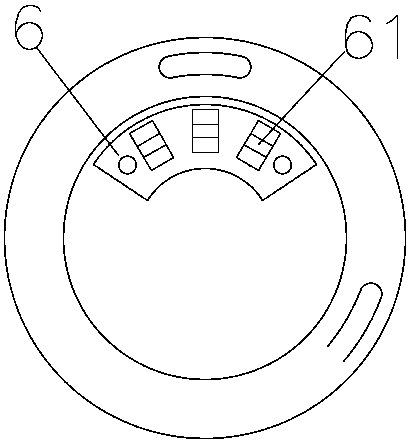
[0033] A sensing device is provided on the part protruding from the end cover at the other end of the rotating shaft; the sensing device includes a code disc having a code bar 5 detachably fixed on the rotating shaft, and a sensor 6 for sensing...

Embodiment 2

[0039] The difference from the above embodiment is that the rotor is provided with 8 teeth, and the code bars are corresponding 8 bars.

[0040]The rotor includes a tooth slot 33 surrounded by the adjacent teeth and the rotor body. The side of the groove and the bottom of the groove are respectively provided with an occlusal groove, the anti-vibration noise reduction block is provided with an occlusal rib 82 that fills the occlusion groove, and the outer side of the anti-vibration and noise reduction block and the outer side of the teeth are coaxial A circular arc surface with the same diameter, the connecting piece is a connecting plate 83 coaxially arranged with the rotor.

[0041] The occlusal slot is a closing slot with a slot width smaller than the inner width of the slot, and a plurality of anti-twist through holes 35 filled with anti-twist ribs 84 are formed on the upper edge of the rotor body perpendicular to the connecting plate. The two ends are respectively fixedly...


PUM


Abstract

The invention relates to the field of household appliances, and specifically relates to a low-noise switched reluctance motor. The motor comprises an end cover as well as a stator and a rotor arranged in the end cover; a rotating shaft connected with the end cover via a bearing penetrates through the rotor, and one end of the rotating shaft stretches out of the end cover to form an output shaft; the rotor comprises a rotor body and a plurality of teeth surrounding the rotor body, an anti-vibration de-noising block is filled between the adjacent teeth, the anti-vibration de-noising blocks are fixedly connected via connectors on two end faces of the rotor, and reinforcing engagement structures are arranged between the rotor and the anti-vibration de-noising blocks. The whole rotor forms a complete cylinder via the anti-vibration de-noising blocks, connecting discs and the like, and gaps between the teeth are filled, so that the dynamic balance of the rotor is improved and then vibration and noise of the motor are reduced. Meanwhile, the rotating inertia of the rotor is increased, the wind resistance is reduced, the noise of air power is reduced and vibration and noise of the motor are greatly reduced.

Description

technical field [0001] The invention relates to the field of home appliance motors, in particular to a low-noise switched reluctance motor. Background technique [0002] At present, brushed motors or DC brushless motors are used for high-speed motors such as household vacuum cleaners, hand dryers, mixers, washing machines, etc. However, brushed motors have the disadvantages of high noise, low efficiency, large vibration, no speed regulation or small speed regulation range. The brush motor has the disadvantages of high-speed operation, large vibration, easy removal of the magnetic tile, and high cost. The existing high-efficiency switched reluctance motor is simple but the rotor mass balance is poor. When it rotates, it generates additional centrifugal force, and the bearing and bracket receive periodic additional The action of centrifugal force, which is transmitted to the casing through the bearing and bracket, causes vibration and noise. SUMMARY OF THE INVENTION [0003...

Claims


Application Information

Patent Timeline
Patent Type & Authority Patents(China)
IPC IPC(8): H02K1/22H02K11/21
CPCH02K1/22
Inventor 江林飞
Owner HUZHOU YONGCHANG BEISHITUO ELECTRIC APPLIANCE INDAL
Why Eureka
Try Eureka