Pull-up exerciser

A technology of pull-ups and exercise equipment, which can be used in sports accessories, gymnastics equipment, muscle training equipment, etc., and can solve problems such as difficult users, inconvenience, and fear

Active Publication Date: 2016-10-05
王国梁
View PDF5 Cites 7 Cited by
  • Summary
  • Abstract
  • Description
  • Claims
  • Application Information

AI Technical Summary

Problems solved by technology

[0003] Then, as mentioned above, since the auxiliary pushing assembly is constantly pushing the supporting plate, when the supporting plate is not in use, it is usually at a certain height position (depending on the push-out length of the auxiliary pushing assembly), so , when the user wants to step on the support board, it will be more inconvenient or even fearful. Of course, there are currently known products that place a stepped platform on the side of the raised support board to facilitate the user to step on the support board. , however, this will also make users feel scared psychologically, fearing that its sinking speed will exceed their expectations, and even produce a repulsive mentality

Method used


Image

  • Pull-up exerciser
  • Pull-up exerciser
  • Pull-up exerciser

Examples


Embodiment 1

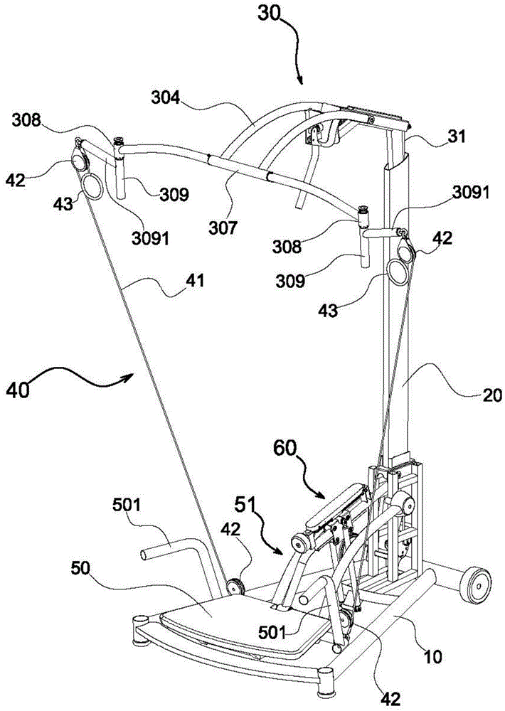
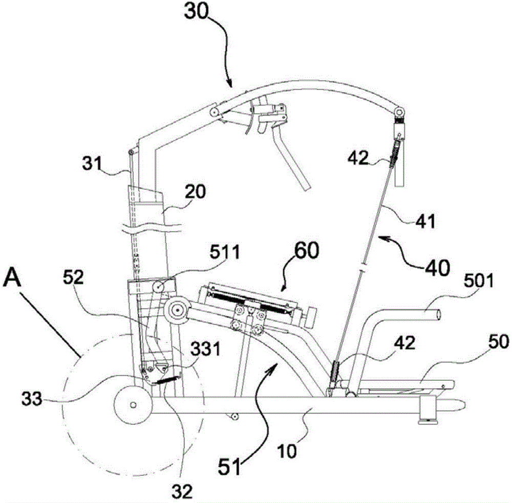
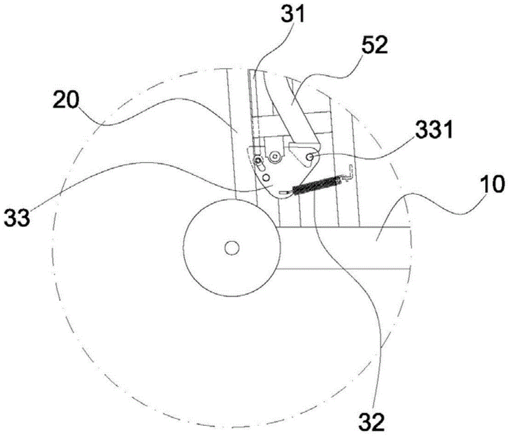
[0037] First, a preferred embodiment of the present invention such as Figure 1 to Figure 7 shown. Depend on Figure 1 to Figure 7It can be seen that the pull-up exerciser of this embodiment includes a base 10 that can stably support all components and a column 20 fixed at the rear of the base 10, and a top cantilever 30 is pivotally connected to the top of the column 20, and the cantilever 30 The end of the cantilever 30 is connected with a linking cable 31, and the other end of the linking cable 31 can drive a locking rotary piece 33 that is constantly pulled by the elastic member 32 to rotate moderately. After that, on the other end of the cantilever 30 One end is provided with pull ring unit 40, so as to cooperate with a stay rope 41 and several pulleys 42 effect, carry out up-and-down displacement stroke with pulling support plate 50 (namely as Figure 7 shown); moreover, a swivel rod assembly 51 is pivotally connected to the bottom end of the column 20, and the other e...

Embodiment 2

[0047] Of course, more like Figure 15 As shown, the present invention can use the action of an electric motor 70 to replace the manual knob 611, so that the auxiliary pushing force of the spring air cylinder 63 can be adjusted more quickly.

[0048] In order to avoid confusion caused by too many reference signs, some drawings are only marked with corresponding reference signs for specific key points, so as to match the specific exclusive content of each section of the manual, so that it is easy to clearly see the indicators, please forgive me check.


PUM


Abstract

The invention relates to a pull-up exerciser. The pull-up exerciser comprises a base and a stand column. The top end of the stand column is connected with a top cantilever in a pivoted mode, the tail end of the cantilever is connected with a linkage cable in a linked mode, the other end of the linkage cable drives a clamping-pulling rotating piece to rotate, the clamping-pulling rotating piece is constantly pulled by an elastic part, and a pull ring unit is arranged at the other end of the cantilever to pull a supporting plate to move vertically in cooperation with a pull rope and a plurality of pulleys. The bottom end of the stand column is connected with a rotating rod assembly in a pivoted mode, the other end of the rotating rod assembly is connected with the supporting plate in a pivoted mode, and an auxiliary pushing unit is arranged between the rotating rod assembly and the base and used for providing upward pushing force for the supporting plate. A linkage hook rod is arranged at the first axis point of the rotating rod assembly and connected with the rotating rod assembly coaxially, and the linkage hook rod cooperates with a corresponding hook column of the clamping-pulling rotating piece to constantly lock the low-point static position of the rotating rod assembly and the supporting plate. Only when the supporting plate bears gravity, the cantilever is pulled downwards, and the linkage rod hook is unlocked from the clamping-pulling rotating piece, can the supporting plate be pulled by the pull ring unit; when the external force of the pull ring unit disappears, the supporting plate descends under continuous gravity and restores to be locked to the low-point static position.

Description

technical field [0001] The invention belongs to the field of pull-up exercise equipment, and relates to a pull-up exercise device. Background technique [0002] The so-called "pull-up exerciser" is basically a kind of indoor sports equipment that simulates the "horizontal bar" or "rings" exercise of gymnastics. Of course, it can also be used to stretch the upper limbs or squat the lower limbs. The types of body movements depend on the user's familiarity with the equipment and their own exercise needs. It can be described as an extremely diverse and excellent indoor exercise and fitness equipment; The load source of motion gravity. Therefore, in design, in order to prevent the user's physical strength from being unable to load his own body weight for many times, an auxiliary pushing component (such as a spring pneumatic cylinder, etc.) is usually provided under the support plate to help the user To apply force, in short, when the user pulls down the pull ring unit located on...

Claims


Application Information

Patent Timeline
IPC IPC(8): A63B23/12A63B21/068A63B23/04
Inventor 王国梁
Owner 王国梁
Why Eureka
Try Eureka