
A horizontal clamping device

A clamping device and horizontal shifting technology, which is applied in the direction of laboratory appliances, supporting appliances, chemical instruments and methods, etc., can solve the problem of low efficiency of picking and placing the microplate, falling of the microplate, and the danger of taking and placing the microplate And other issues

Active Publication Date: 2018-01-09
SUZHOU JIEMEI ELECTRONICS
View PDF5 Cites 0 Cited by
  • Summary
  • Abstract
  • Description
  • Claims
  • Application Information

AI Technical Summary

Problems solved by technology

[0002] In the modern laboratories of colleges and universities, environmental protection, scientific research, health and epidemic prevention stations, petroleum, chemical, medical and other units, the microplate is a commonly used tool, its shape is mostly rectangular, and its upper end is inserted with dense test tubes. , the test tubes are often filled with virus-containing substances, and there will be certain dangers when operators take and place the microtiter plate, and the microtiter plate is often placed in a special area such as the bottom of the incubator, so the operator takes it with bare hands The microplate plate is very inconvenient, prone to the danger of the plate falling, and the efficiency of picking and placing the plate is not high, so a convenient pick-and-place device that can directly touch the plate instead of the operator's hand is needed to move the plate

Method used


Image

  • A horizontal clamping device
  • A horizontal clamping device
  • A horizontal clamping device

Examples


Embodiment Construction

[0022] Below in conjunction with specific embodiment, further illustrate the present invention. It should be understood that these examples are only used to illustrate the present invention and are not intended to limit the scope of the present invention. In addition, it should be understood that after reading the teachings of the present invention, those skilled in the art can make various changes or modifications to the present invention, and these equivalent forms also fall within the scope defined by the appended claims of the present application.

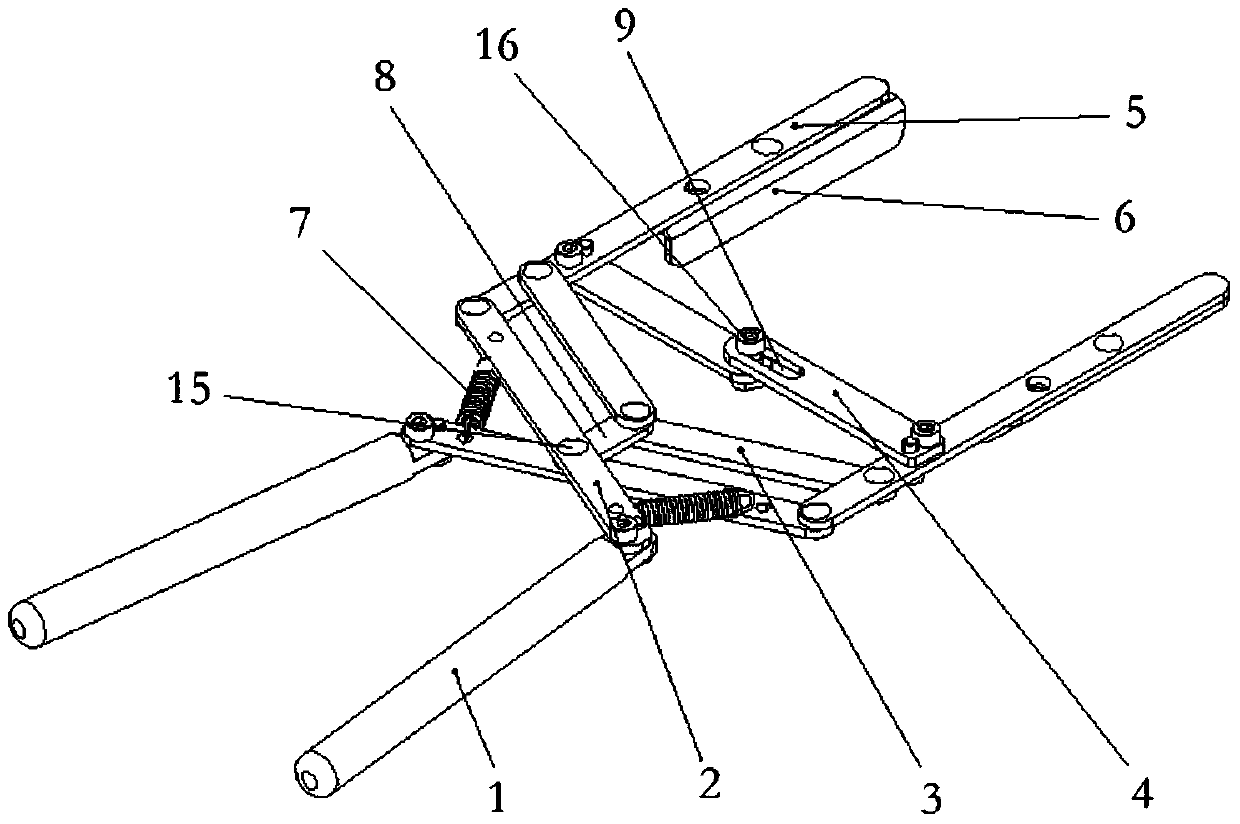
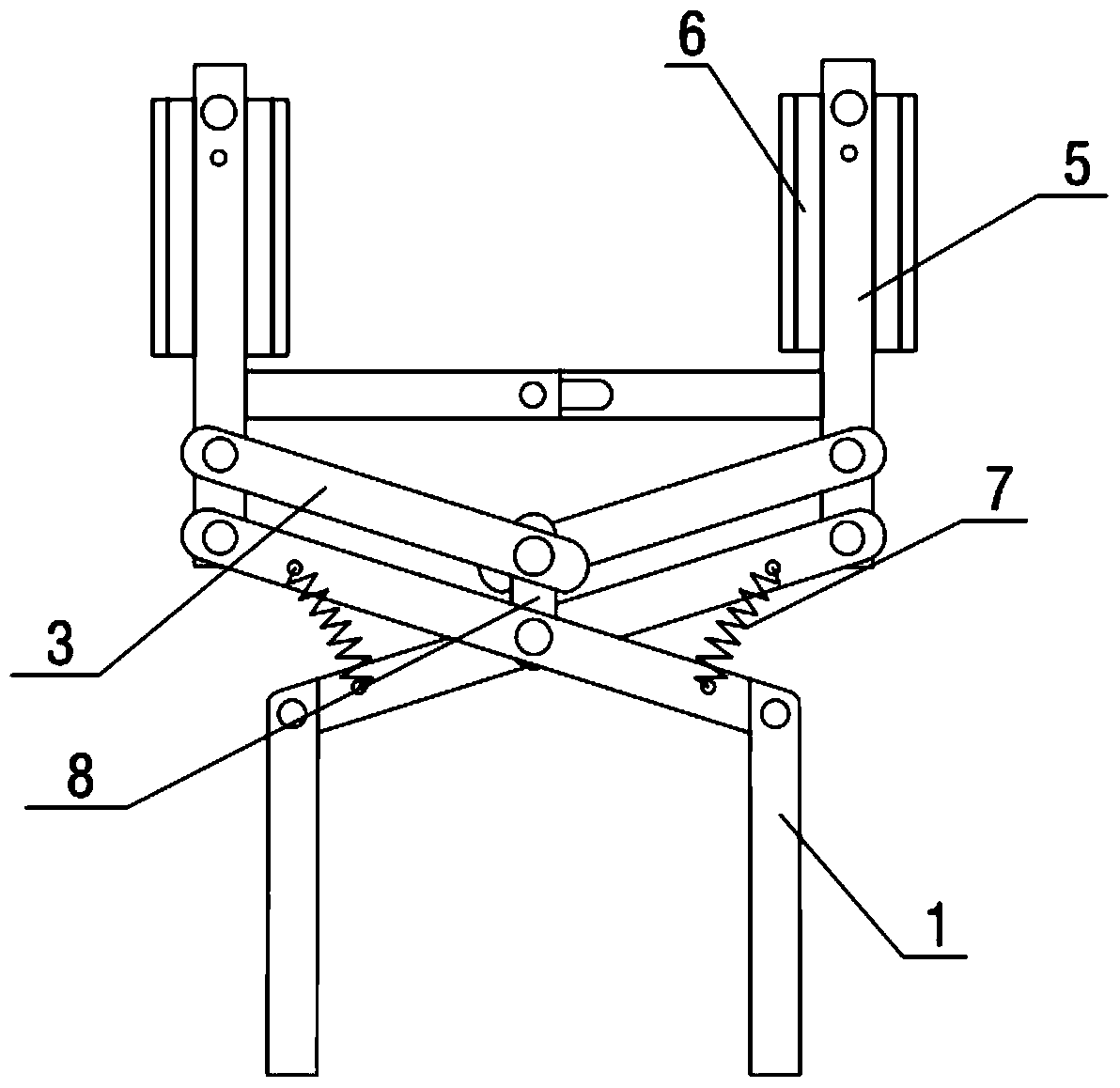
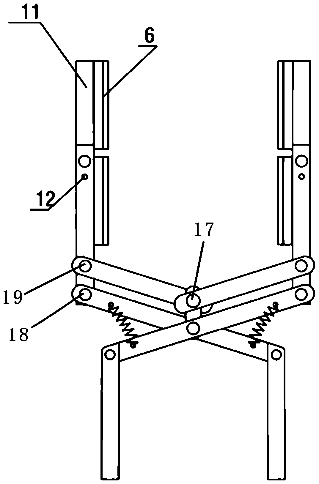
[0023] Such as Figure 1-4 As shown, the embodiment of the present invention relates to a clamping device for horizontal shifting, including a handle 1, a main link 2 and a clamping rod 5, the handle 1 is fixed on one end of the main link 2, and two main links The rod 2 takes the rotating shaft I15 as the center of rotation and is distributed left and right; the other ends of the two main connecting rods 2 are connected to one...


PUM


Abstract

The invention relates to a horizontal movement and placement clamping device comprising handles, main connection bars and clamping bars. The handles are fixed on the main connection bars, and are distributed left and right with a rotation shaft as a rotation center. The other ends of the main connection bars are pinned with one ends of the clamping bars, and rotate around rotation pins. Limit bars are arranged at appropriate positions of the clamping bars, such that outward rotation is prevented when rotation happens at the places where the clamping bars are connected with the main connection bars, and the clamping device can reset automatically. The two clamping bars are connected through a pair of directional movement bars which can perform relative sliding. Clamping blocks are symmetrically arranged on the opposite side walls of the two clamping bars. When the handles perform circular motions around the rotation shafts under manual driving, through a series of leverage effects, the horizontal movement of the left and right side clamping blocks is realized, and an object can be clamped or released. The device has a simple structure, and can realize movement and placement of objects, especially straight-edge objects, in a small space.

Description

technical field [0001] The invention relates to the field of transfer devices, in particular to a clamping device for horizontal transfer. Background technique [0002] In the modern laboratories of colleges and universities, environmental protection, scientific research, health and epidemic prevention stations, petroleum, chemical, medical and other units, the microplate is a commonly used tool, its shape is mostly rectangular, and its upper end is inserted with dense test tubes. , the test tubes are often filled with virus-containing substances, and there will be certain dangers when operators take and place the microtiter plate, and the microtiter plate is often placed in a special area such as the bottom of the incubator, so the operator takes it with bare hands The microplate plate is very inconvenient, prone to the danger of the plate falling, and the efficiency of picking and placing the plate is not high, so a convenient pick-and-place device that can directly touch ...

Claims


Application Information

Patent Timeline
Patent Type & Authority Patents(China)
IPC IPC(8): B01L9/00
Inventor 黄维雷陈志明
Owner SUZHOU JIEMEI ELECTRONICS
Learn More