Flush toilet

A toilet and flushing technology, applied in flushing toilets, water supply devices, flushing equipment with water tanks, etc., can solve the problems of water flying out of the toilet, forming an inner edge, and lowering the height of the inner edge, etc.

Inactive Publication Date: 2016-10-05
TOTO LTD
View PDF12 Cites 2 Cited by
  • Summary
  • Abstract
  • Description
  • Claims
  • Application Information

AI Technical Summary

Problems solved by technology

[0008] However, if such an inner edge with high cleaning properties is used, since the upper part of the inner edge is formed to have a large arc, the height of the inner peripheral surface of the inner edge becomes low, and it cannot be formed in an overhanging shape. In the inner edge part, when the cleaning water spouted from the inner edge water spout has a relatively high instantaneous flow rate, a new problem occurs that the water easily crosses the inner peripheral surface of the inner edge part and flies out of the toilet
When a direct pressure type water supply device is used for a flush toilet having a rim shape with high cleanability, this problem occurs more remarkably because the flushing water spouted from the rim spout has a high instantaneous flow rate.

Method used


Image

  • Flush toilet
  • Flush toilet
  • Flush toilet

Examples


Embodiment Construction

[0045] Next, a flush toilet according to an embodiment of the present invention will be described with reference to the drawings.

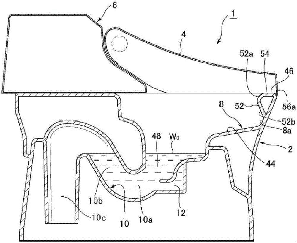
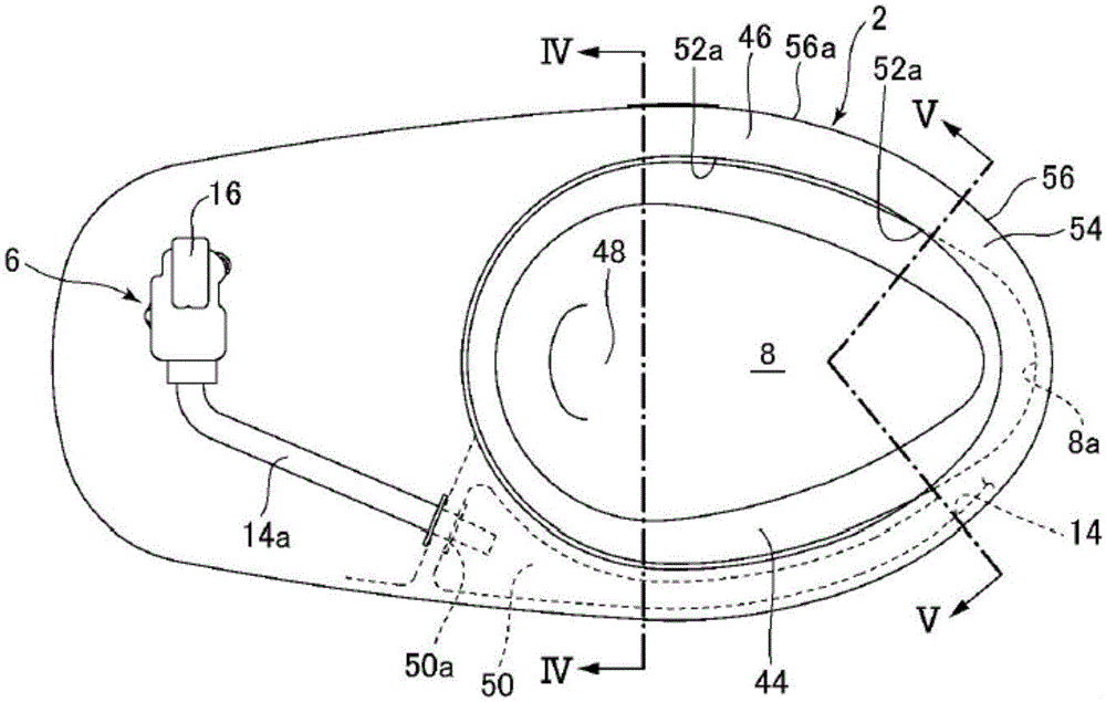
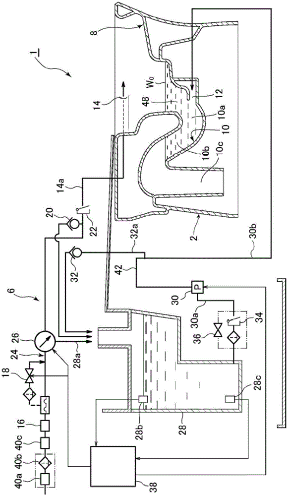
[0046] First, through Figure 1 to Figure 3 The structure of the flush toilet according to the first embodiment of the present invention will be described. here, figure 1 It shows the state of the water supply device and the lid of the flush toilet according to the first embodiment of the present invention viewed from the side, and is a partial cross-sectional view showing the inside of the toilet body along the central section, figure 2 It is a schematic plan view showing a state where a cover and a part of the water supply device are removed from the flush toilet according to the first embodiment of the present invention, image 3 It is an overall configuration diagram showing the flush toilet according to the first embodiment of the present invention.

[0047] Such as figure 1 and figure 2 As shown, the flush toilet 1 according to the fi...


PUM


Abstract

A flush toilet with a rim portion is provided, wherein the rim inside wall portion comprises a rim inside wall upper sloped surface, wherein the sloped surface is inclined on the lower part of the inner side of the upper part area, and the rim inside wall upper sloped surface improves visibility of the user and cleaning of the inner rim. Furthermore, flush water can be constrained from splashing outside the bowl portion of the flush toilet by traveling by centrifugal force along the rim inside wall upper sloped surface from the inside surface formed at a relatively low height. The flush toilet comprises a dirt bearing surface, a bowl part of the inner rim part, a water spitting part for people to spit clean water to the bowl part, and a water feeding device. The rim portion of the flush toilet (1) includes a rim inside wall portion (52); the rim inside wall portion (52) comprises a rim inside wall upper sloped surface (52a), and an inside surface vertically extending straight up to the rim inside wall upper sloped surface (52a); and a water supply apparatus (6) comprises a constant flow rate valve (16) for spouting a predetermined constant flow rate of flush water from a water spouting portion.

Description

technical field [0001] The present invention relates to a flush toilet, and more particularly to a flush toilet that cleans a toilet body with cleansing water supplied from a cleansing water source to discharge dirt. Background technique [0002] Conventionally, the following flush toilets are known. As described in Patent Document 1, in the flush toilets, a gravity-fed water storage tank is provided as a water supply device at the rear upper part of the flush toilet. The inner peripheral surface of the rim portion is formed so as to stand in a substantially vertical direction, and the washing water jetted from the rim water discharge port formed in the front side region performs washing while swirling in the bowl portion. [0003] Patent Document 1: Japanese Patent Laid-Open No. 2013-44178 [0004] When such a flush toilet does not use a gravity-fed water storage tank, but wants to apply a direct-pressure water supply device that is directly connected to a water pipe or th...

Claims


Application Information

Patent Timeline
Patent Type & Authority Applications(China)
IPC IPC(8): E03D11/06E03D11/13
CPCE03D11/06E03D11/13E03D5/01E03D11/08E03D2201/40E03D1/00
Inventor 头岛周浅田协二山川聪士溝口和吉北村正树
Owner TOTO LTD
Why Eureka
Try Eureka