A transformer spiral winding cable arrangement

A spiral type and transformer technology, applied in the field of transformer manufacturing, can solve the problems of power supply company and user loss, endanger personal and property safety, impact on power supply network, etc., achieve the effect of reducing the probability of burning, simple structure, and free position adjustment

Active Publication Date: 2018-08-21
CHINA RAILWAY ELECTRICAL IND CO LTD
View PDF7 Cites 0 Cited by
  • Summary
  • Abstract
  • Description
  • Claims
  • Application Information

AI Technical Summary

Problems solved by technology

The spiral coil has a simple structure and a wide range of applications. However, during the winding process, due to the large number of windings in parallel, the force on individual coils is uneven. Bending or buckling instability, this kind of deformation can easily lead to the burning of the transformer. Once the transformer is burned, it will not only have a huge impact on the power supply network, but also endanger the safety of personal property and cause huge losses to the power supply company and users.

Method used


Image

  • A transformer spiral winding cable arrangement

Examples


Embodiment Construction

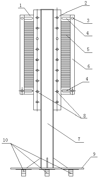
[0010] The present invention will be further described below in conjunction with the accompanying drawings and specific embodiments.

[0011] Such as figure 1 As shown, this embodiment includes a threading board 1 , a wire blocking board 6 , an adjusting board 2 and a bracket 7 . Both ends of the threading plate 1 are provided with 32 equidistant threading slots 5 and four retaining lines symmetrically distributed relative to the central vertical axis (48, 40, 24, etc. can also be set as required in multiples of 4) Plate installation elongated holes 4. The strip holes 4 are located on the upper and lower edges of the threading board 1 . The upper and lower ends of the left and right middle positions of the threading plate 1 are provided with four mounting holes of the regulating plate. The adjusting plate 2 is welded and fixed on the support 7, on which two rows of vertical fixing holes 8 are opened. The threading plate 1 is fixed on the adjusting plate 2 by screws to adju...


PUM


Abstract

The invention discloses a spiral winding arranging device of a transformer. Equal internal threading grooves symmetrically distributed relative to the central vertical axis and four installation long-strip holes for a wire baffle are formed in the two ends of a threading plate, wherein the number of the equal internal threading grooves is multiples of four. The long-strip holes are located in the upper edge and the lower edge of the threading plate, and four installation holes for an adjusting plate are formed in the upper ends and the lower ends of the left and right middle positions of the threading plate. An adjusting plate is fixed to a support and provided with two vertical twos of fixing holes. The wire baffle is fixed to the threading plate in a left-right position adjustable mode. The lower end of the support is fixed to a base, or a hanging plate is fixed to the upper end of the support. By means of the spiral winding arranging device, a wire can be neatly wound in parallel, the tension force of the wire wound in parallel is consistent, the probability of burning of the transformer is reduced, and the safety performance of the transformer is improved; besides, both a single-spiral structure and a dual-spiral structure can be used, and thus university is high.

Description

technical field [0001] The invention belongs to the field of transformer manufacturing, and relates to a transformer spiral winding cable puller. Background technique [0002] At present, the low-voltage windings of medium and large-capacity transformers mostly adopt spiral type due to the large current winding structure, and the number of winding coils is an integer multiple of 4, and the number does not exceed 48 at most. The spiral coil has a simple structure and a wide range of applications. However, during the winding process, due to the large number of windings in parallel, the force on individual coils is uneven. Bending or buckling instability, this kind of deformation can easily lead to the burning of the transformer. Once the transformer is burned, it will not only have a huge impact on the power supply network, but also endanger the safety of personal property and cause huge losses to the power supply company and users. Contents of the invention [0003] The pu...

Claims


Application Information

Patent Timeline
Patent Type & Authority Patents(China)
IPC IPC(8): H01F41/064H01F41/082
Inventor 徐志华洪颖柴淑颖张冬冬马泽彬
Owner CHINA RAILWAY ELECTRICAL IND CO LTD
Why Eureka
Try Eureka