Constant tension control device based on time calculation rolling diameter

A control device and time calculation technology, which is applied in transportation and packaging, delivery of filamentous materials, thin material processing, etc., can solve the problem that the speed cannot be increased automatically, the wire rope is twisted unevenly, and it is not enough to ensure the constant pay-off speed and constant tension pay-off

Inactive Publication Date: 2015-09-16
金新民
View PDF11 Cites 6 Cited by
  • Summary
  • Abstract
  • Description
  • Claims
  • Application Information

AI Technical Summary

Problems solved by technology

Once the pay-off tension is adjusted, it can no longer be adjusted after turning on the machine, you can only let it go
During the pay-off process, the pay-off speed tends to decrease with the decrease of the roll diameter of the I-shaped wheel. In order to ensure constant line speed and constant tension, the speed of the I-shaped wheel must be increased. Due to the impact of the damping rope on the damping wheel The braking torque has not changed, and the speed of the I-shaped wheel cannot be automatically increased due to the reduction of the capacity of the I-shaped wheel, so it is not enough to ensure the constant pay-off speed and constant tension pay-off
At the same time, this tension control method mainly relies on manual proficiency and responsibility, so it is greatly affected by human factors, and the tension control accuracy is low, resulting in uneven twisting of the steel wire rope, and poor surface smoothness and looseness of the steel wire rope. Guarantee, which in turn affects the appearance quality and bearing capacity of the wire rope, greatly shortening the service life of the wire rope

Method used


Image

  • Constant tension control device based on time calculation rolling diameter
  • Constant tension control device based on time calculation rolling diameter
  • Constant tension control device based on time calculation rolling diameter

Examples


Embodiment Construction

[0016] The present invention will be further described below in conjunction with the accompanying drawings and specific embodiments.

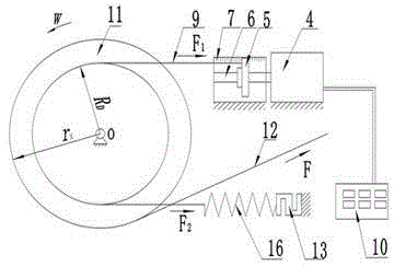
[0017] The present invention is realized by following measures, and its method is, set up the winding model of steel wire 12 on the I-shape wheel 11, calculate the size of real-time volume diameter value with the method based on time in the unwinding process, then, the volume diameter of calculation The value is put into the control program, and a control signal is sent to control the rotation direction and step distance of the screw stepper motor 4, thereby adjusting the tightness of the damping rope 9 to achieve constant tension control.

[0018] Specifically, the implementation process of each step includes the following:

[0019] 1. Determine the winding model of the steel wire 12

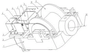
[0020] The steel wire 12 is wound on the I-shaped wheel 11 and adopts a wire arrangement mechanism. The function of the wire arrangement mechanism is to make t...


PUM


Abstract

The invention provides a constant tension control device based on a time calculation rolling diameter. The constant tension control device comprises a bobbin rack and an H-shaped wheel arranged on the bobbin rack in a rotating mode. A power supply for supplying power is arranged on the bobbin rack. A motor is arranged on one side of the bobbin rack. A motor shaft of the motor is fixedly connected with a lead screw. A screw and nut pair is arranged on the lead screw. A tension sensor is arranged on the other side of the bobbin rack. The screw and nut pair is connected with the tension sensor through a damping rope. A spring is connected between the tension sensor and the damping rope. A rotating wheel matched with the damping rope is fixedly arranged on the H-shaped wheel. A tension controller is arranged on the bobbin rack. The tension sensor and the motor are both connected with the tension controller. Through the control method for controlling the tightness of the damping rope through a lead screw stepping motor, according to the constant tension control device, the tension of each strand of steel wires is kept constant in the transmission process, and tension between the steel wires tends to be constant.

Description

technical field [0001] The invention relates to steel wire rope processing equipment, in particular to a constant tension control device for calculating coil diameter based on time. Background technique [0002] At present, the production equipment used by most domestic steel wire rope manufacturers, whether it is a stranding machine or a rope forming machine, uses a simple damping belt. During twisting, workers manually adjust the tension, and adjust the tension between the nut and the spring. Adjust the tightness of the free end of the damping rope on the damping wheel to adjust the tension of the steel wire or rope strands on each pay-off I-shaped wheel. Once the pay-off tension is adjusted, it cannot be adjusted after turning on the machine, and it can only be left to itself. During the pay-off process, the pay-off speed tends to decrease with the decrease of the roll diameter of the I-shaped wheel. In order to ensure constant line speed and constant tension, the speed ...

Claims


Application Information

Patent Timeline
Patent Type & Authority Applications(China)
IPC IPC(8): B65H59/38
Inventor 赵京陈宗毅冯凡金新民
Owner 金新民
Why Eureka
Try Eureka