Three-pass band filter

A technology of filters and three-pass bands, applied in waveguide devices, electrical components, circuits, etc., can solve problems such as complex filter feed structures

Active Publication Date: 2016-10-05
QINGDAO HAIER ELECTRONICS +1
View PDF7 Cites 12 Cited by
  • Summary
  • Abstract
  • Description
  • Claims
  • Application Information

AI Technical Summary

Problems solved by technology

[0004] One of the purposes of the present invention is to provide a three-pass band f

Method used


Image

  • Three-pass band filter
  • Three-pass band filter
  • Three-pass band filter

Examples


Embodiment Construction

[0019] In the following detailed description, numerous specific details are set forth in order to provide a thorough understanding of the present invention. However, it will be understood by those skilled in the art that the present invention may be practiced without these specific details. In other instances, well-known methods, procedures, components and circuits have not been described in detail so as not to obscure the present invention.

[0020] In order to facilitate a quicker understanding of the illustrative embodiments of the present invention, the main idea of ​​the present invention is briefly described below:

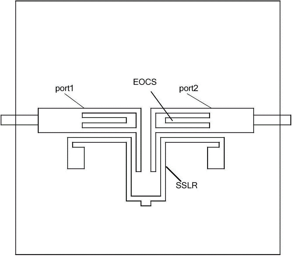
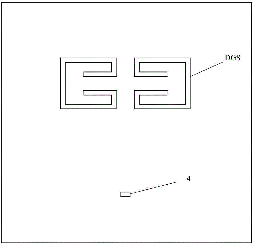
[0021] For multi-band band-pass filters, the traditional way is to design the three-band BPF by adjusting the impedance ratio and length ratio of each part of the stepped impedance resonator (SIR). In recent years, the defective ground resonator structure (DGSR) has become more and more popular in filter design, because it can not only increase the passband...


PUM


Abstract

A three-pass band filter comprises a non-conductive substrate, an input feeder line and an output feeder line, a defect ground type resonant structure and a short circuit stub type resonant structure are arranged on the two surfaces of the substrate respectively, and the input feeder line and the output feeder line are arranged on the surface of the substrate having the short circuit stub type resonant structure and are located between the defect ground type resonant structure and the short circuit stub type resonant structure, wherein the input feeder line, the short circuit stub type resonant structure and the output feeder line are coupled to form a first radio frequency access possessing a first pass band and a third pass band, and the input feeder line, the defect ground type resonant structure and the output feeder line are coupled to form a second radio frequency access possessing a second pass band. According to the present invention, the defect ground type resonant structure and the back laminated short circuit stub type resonant structure form the three pass bands of the three-pass band filter, so that the three-pass band filter is simple in structure, guarantees a filtering effect, and enables the reliability to be improved.

Description

technical field [0001] The invention relates to the technical field of passive filters, in particular to a three-pass band filter. Background technique [0002] It has become a trend in recent years to have wireless communication systems and RF front-ends with multiple working frequency bands at the same time. Therefore, it is also necessary to design a high-performance multi-pass band-pass filter. [0003] At present, how to design a three-pass band filter with simple structure, good selectivity and strong out-of-band rejection is an important problem in the design field. Contents of the invention [0004] One of the objects of the present invention is to provide a three-pass band filter to solve the problem of complex feeding structure of the filter in the prior art. [0005] In some demonstrative embodiments, the three-pass band filter includes: a substrate of non-conductive material, an input feeder and an output feeder, and a defective ground resonant structure and ...

Claims


Application Information

Patent Timeline
IPC IPC(8): H01P1/212
Inventor 彭彪李书芳王帅翟翌立刘超
Owner QINGDAO HAIER ELECTRONICS
Why Eureka
Try Eureka