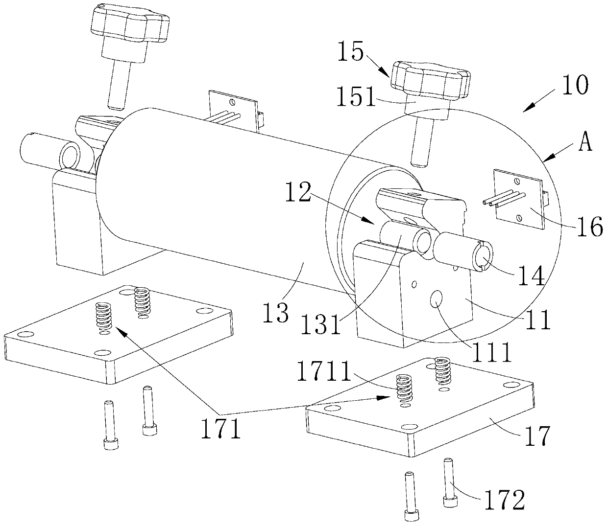
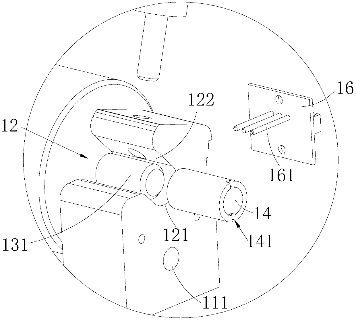
High current pole type battery clamp
A battery fixture, high current technology, applied in the direction of clamping/spring connection, measuring device casing, etc., can solve the problems of unreliable high current overcurrent capability, poor voltage parameter acquisition accuracy, small conductive contact area, etc., to achieve high current Reliable overcurrent capability, suitable for batch use, and low contact resistance
- Summary
- Abstract
- Description
- Claims
- Application Information
AI Technical Summary
Problems solved by technology
Method used
Image

Examples
Embodiment Construction
[0022] In order to make the object, technical solution and advantages of the present invention clearer, the present invention will be further described in detail below in conjunction with the accompanying drawings and embodiments. It should be understood that the specific embodiments described here are only used to explain the present invention, not to limit the present invention.
[0023] Such as Figure 1~2 Shown is the preferred embodiment provided by the present invention.
[0024] It should be noted that, when an element is referred to as being “fixed on” or “disposed on” another element, it may be directly on the other element or there may be an intervening element at the same time. When an element is referred to as being "connected to" another element, it can be directly connected to the other element or intervening elements may also be present.
[0025] It should also be noted that the orientation terms such as left, right, up, and down in this embodiment are only re...
PUM
 Abstract
Description
Claims
Application Information
 - R&D Engineer
- R&D Manager
- IP Professional
- Industry Leading Data Capabilities
- Powerful AI technology
- Patent DNA Extraction
Browse by: Latest US Patents, China's latest patents, Technical Efficacy Thesaurus, Application Domain, Technology Topic.
© 2024 PatSnap. All rights reserved.Legal|Privacy policy|Modern Slavery Act Transparency Statement|Sitemap