Pedal-controlled electric apparatus, electric vehicle, and method of driving, braking and range extending of the same

A technology of electric devices and electric vehicles, applied in electromechanical devices, electric vehicles, control systems, etc.

Inactive Publication Date: 2016-10-05
广东捷翔动力科技有限公司
View PDF7 Cites 0 Cited by
  • Summary
  • Abstract
  • Description
  • Claims
  • Application Information

AI Technical Summary

Problems solved by technology

[0007] The purpose of the present invention is to overcome the defects of the internal structure of the existing DC motor for electric vehicles, provide an internal structure different from the traditional design, and at the same time change the direct current into a sequence of alternating non-energized directions through the power modulator Current power supply scheme, simple structure, large torque, and easy process

Method used


Image

  • Pedal-controlled electric apparatus, electric vehicle, and method of driving, braking and range extending of the same
  • Pedal-controlled electric apparatus, electric vehicle, and method of driving, braking and range extending of the same
  • Pedal-controlled electric apparatus, electric vehicle, and method of driving, braking and range extending of the same

Examples


Embodiment 1

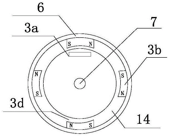
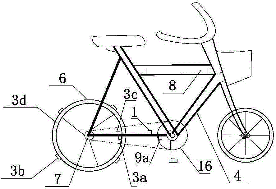
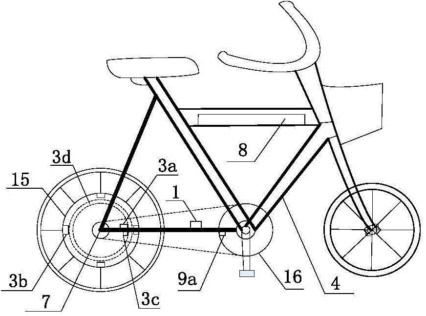
[0094] An electric device and a two-wheeled vehicle containing the device, the local structure of the supporting vehicle frame 4 is as follows: Figure 1c As shown, the circumference of the wheel is 1000mm, and the battery pack 8b is a 24V12Ah lithium iron phosphate battery installed inside the frame. The rotating body of the electric device adopts a double-annular titanium-aluminum alloy hub 15 with a rotation axis and a circumference of 100mm, which is arranged on the rear wheel. A disc with a fixed shaft is set on the coaxial 7 inside the hub, and the outer fixed shaft of the disc is The mechanical parameters are designed with reference to the data of the supporting two-wheeled vehicle, and are used to replace the fixed axle of the conventional two-wheeled vehicle for installation. A stator unit 3a is installed on the disc; 8 rotor units made of NdFeB are arranged on the inner edge of the hub.

[0095] The rotor unit is processed into a small arc-shaped box-shaped unit with...

Embodiment 2

[0103]The materials for setting 8 rotor units on the inner edge of the hub 15 described in Example 1 are transformed into 4 NdFeB and 4 conventional magnetizers, and the NdFeB rotor units and the magnetizer rotor units are evenly arranged one by one.

[0104] The pulse digital technical solution adopted by the power supply modulator is similar to that of Embodiment 1, and the working logic is adjusted as follows: when the winding of the stator unit is energized, within 4s, the corresponding wheel rotation cycle is automatically increased in each next cycle based on 6A The current sequence of 10% output intensity, waits for the next work command of the drive control device from the 5th second: if the drive control device 9a has no input command, the power modulator 1 sleeps; if the command given by the drive control device is to accelerate, then At the moment when the power modulator starts to energize in the next cycle, it executes T 1 with (T 2 +T 0 ) ratio of 1:6 current s...

Embodiment 3

[0107] The hub 15 of the electric device described in Embodiment 1 is changed to a rotating body 6 in the form of a single annular titanium-aluminum alloy ring with a rotating shaft and a circumference of 100 mm, and a disc with a fixed shaft is set on the coaxial 7 in the rotating body. The external mechanical parameters of the fixed shaft of the disc are also designed with reference to the data of the supporting two-wheeled vehicle, and are installed to replace the fixed wheel shaft of the conventional two-wheeled vehicle. A stator unit 3a is installed on the disc; The combined deceleration / torque conversion device 2 is installed coaxially with the rotating body, and the deceleration ratio is 10:1; the deceleration / torque conversion device is provided with a number of mechanical holes, one end of the spokes is perforated and fixed, and the other end is fixed. Even the inner edge of the hub (wheel rim) makes the electric device realize the transmission of the wheel 5, such as ...


PUM


Abstract

The invention discloses a pedal-controlled electric apparatus and an electric vehicle. The electric apparatus comprises a power supply modulator, a driving control apparatus, a stator unit, rotor units, a swivel and a pedal sprocket wheel, wherein the swivel is an annular mechanical ring with a rotation axis, and at least two rotor units are arranged on the swivel at intervals; the material of each rotor unit includes a permanent magnet or a magnetizer, or combination of the permanent magnet and the magnetizer; the number of the stator unit is at least one; the relative air gap between the stator unit and the rotor unit period is less than or equal to 80mm; the driving control apparatus is arranged at a fixed part corresponding to the pedal sprocket wheel period or is designed and manufactured in an integrated way; and the power supply modulator acquires a user command through the driving control apparatus/electromagnetic brake apparatus and then outputs a sequential current correspondingly to enable the electric apparatus to realize driving/braking. The electric vehicle includes vehicle frame, a battery pack, at least one wheel, and at least one set of electric apparatus, wherein a range extending system is used for replenishing the secondary battery pack with electric energy in the set logic state.

Description

technical field [0001] The invention relates to the field of electric vehicle and its power source power design, in particular to a mechanical structure of an electric device, a sequential current design method for driving and braking, and a range-extending method for the electric vehicle. Background technique [0002] At present, the mainstream of the electric bicycle market is to use electric wheels. This type of electric wheel actually deforms the motor traditionally installed on the shaft in the hub; in the narrow sense, the hub refers to the flange, bearing seat and other parts connected to the transmission shaft. At present, domestic users It refers more to the rim, and the hub described in this manual covers two parts, the hub and the rim in a narrow sense. [0003] The power supply drive of electric bicycles on the market is mostly set to handle rotation control. This design is one of the safety hazards of electric bicycle accidents that have continued to rise in rec...

Claims


Application Information

Patent Timeline
Patent Type & Authority Applications(China)
IPC IPC(8): H02K29/00H02K29/06H02K1/12H02K1/27H02P6/00H02P6/24B62M6/60
CPCY02T10/64
Inventor 刘粤荣刘通
Owner 广东捷翔动力科技有限公司
Why Eureka
Try Eureka