
Wheel hub system of electric vehicle and driving method, braking method and electric energy supplementing method of wheel hub system

An electric wheel hub, electric vehicle technology, applied in the direction of electric braking system, electric vehicle, motor control, etc., to achieve obvious energy saving effect

Inactive Publication Date: 2016-07-27
NANJING MENGQI INTELLIGENT TECH +1
View PDF7 Cites 0 Cited by
  • Summary
  • Abstract
  • Description
  • Claims
  • Application Information

AI Technical Summary

Problems solved by technology

[0006] The purpose of the present invention is to overcome the defects of existing electric vehicles equipped with wheel hub motors, to provide an electric wheel hub device with sequential current control and a mechanical structure different from traditional designs, and to provide a range-extending technology based on electric vehicle supplementary electric energy scheme, simple structure, large torque, and easy process

Method used


Image

  • Wheel hub system of electric vehicle and driving method, braking method and electric energy supplementing method of wheel hub system
  • Wheel hub system of electric vehicle and driving method, braking method and electric energy supplementing method of wheel hub system
  • Wheel hub system of electric vehicle and driving method, braking method and electric energy supplementing method of wheel hub system

Examples


Embodiment 1

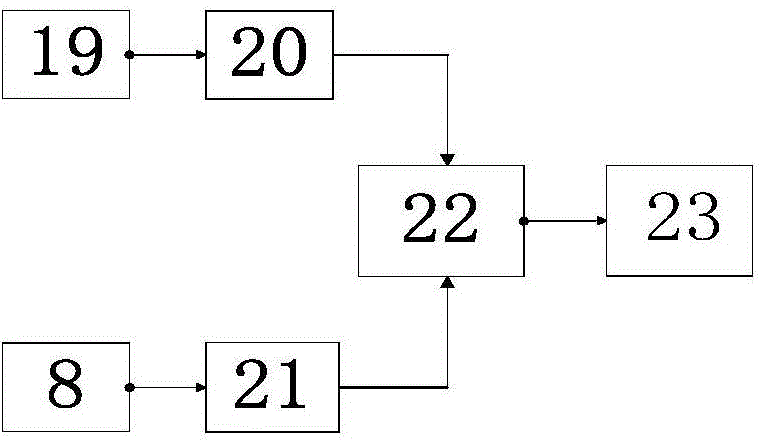
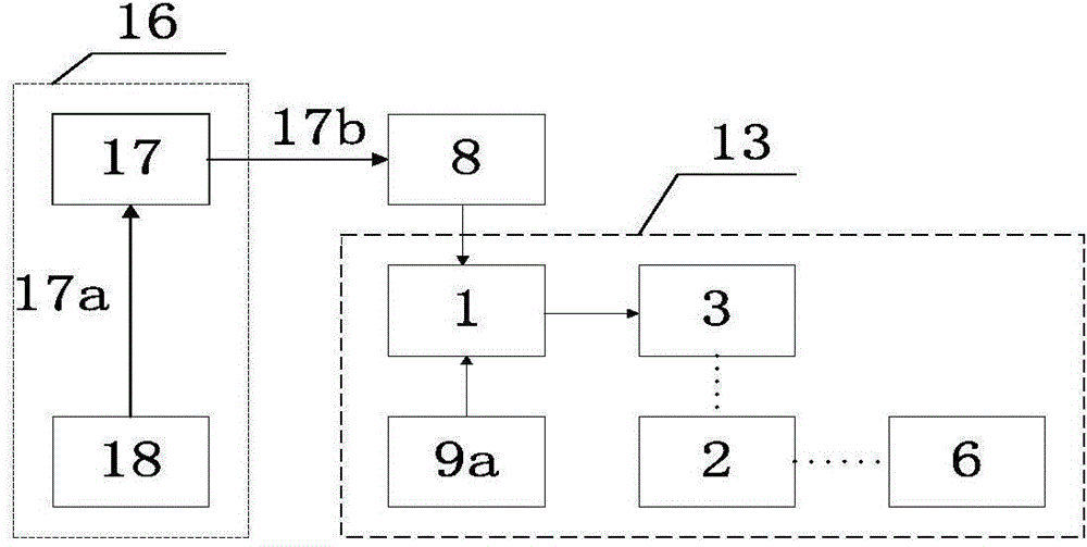
[0097] A wheel hub system of a power-assisted electric tricycle, including an electric hub device 13, a battery pack 8 and a range-extending system 16; the electric hub device is arranged on the front wheel, and its supporting frame 4 and mechanical partial schematic structure are as follows: Figure 10a As shown; the battery pack 8 selects a nominal 48V20Ah lead-acid gel battery and is installed on the lower part of the frame; the range-extending system uses a methanol generator system as an electric energy supplement device 18, and the generator system consists of a methanol fuel tank, a methanol internal combustion engine, and a generator It is combined with a rectifying device; the logic charging device 17 of the range-extending system is mainly composed of functional modules such as a battery pack real-time voltage monitoring module, a constant voltage limited current charging module and a working logic control module, and its input terminal 17a is electrically connected to...

Embodiment 2

[0106] The power supply device of the range-extending system in Example 1 is changed from a methanol generator system to an aluminum-air primary battery; the power modulator 1 is implemented using pulse digital technology, and the core module includes a conventional CPU and a drive module with a design power of 1500W. working logic like Figure 5b As shown, the pulse conversion conditioning circuit is mainly to complete the conversion of the pulse signal into a ladder wave signal, the pulse signal generator mainly generates the required pulse signal, and secondly outputs the peak pulse through the differential circuit, and then passes through the limiting circuit to convert the negative of the peak pulse The half-cycle is filtered out, and the positive half-axis peak pulse is left. The integral circuit composed of an integrated operational amplifier is used for integral accumulation, and a voltage comparator and a control circuit are added to form a complete ladder pulse signal...

Embodiment 3

[0110] Using T on the basis of Example 2 2 Time-domain electrification adds an electromagnetic force braking function to the electric hub device.

[0111] The power supply modulator correspondingly adds a braking signal input terminal 1e to electrically connect the electromagnetic braking device 9b, such as Figure 5c As shown, the electromagnetic braking device is a ten-stage rheostat; when the manual control electromagnetic braking device sends a braking signal, the power modulator cuts off T 1 corresponding to the timing current, start T 2 Time-domain energization, the brake energization time domain is set when the sensing unit 3c senses the rotor unit 3b around the shaft to for arrive is the time period for the 0 degree position.

[0112] The brake current output by the power modulator corresponds to the ten-level resistance of the electromagnetic braking device 9b, which is set to ten-level intensity. The set output current intensity is: the first level is 5A, the...


PUM


Abstract

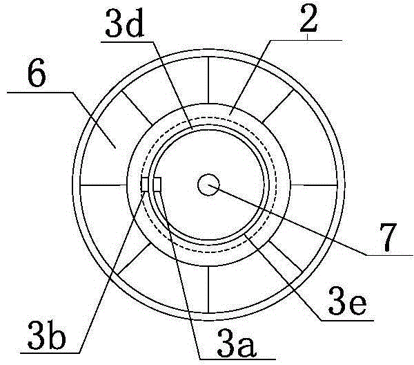
The invention discloses a wheel hub system of an electric vehicle. The wheel hub system comprises an electric wheel hub device, a battery pack and a stroke increasing system; the electric wheel hub device comprises a power source modulator, a speed reduction / moment changing device, a wheel hub, a driving and controlling device and one or more electric devices; each electric device comprises a coaxial rotating body, one or more stator units and one or more magnetizer rotor units; each coaxial rotating body is an annular mechanical ring with a rotating shaft; each rotator unit is arranged on the coaxial rotating body; the stator units are mounted in the corresponding coaxial rotating body, and a relative air gap between each stator unit and the corresponding coaxial rotating body is not greater than 60 mm; the coaxial rotating bodies and the wheel hub are coaxially arranged, and the electric devices and the speed reduction / moment changing device are all arranged in the wheel hub; the power source modulator obtains a command through the driving and controlling device and an electromagnetic braking device and outputs a time sequence current correspondingly, and driving and braking of the electrical wheel hub device are achieved; the stroke increasing system of the wheel hub system supplements electric energy for the battery pack.

Description

technical field [0001] The invention relates to the field of power design of an electric vehicle, in particular to a method for driving and braking an electric device controlled by a sequential current and a method for designing a range extension of a matching electric vehicle. Background technique [0002] The mainstream of the domestic electric bicycle market is to use electric wheels. This type of electric wheel actually deforms the electric motor traditionally installed on the shaft in the hub, and transmits the torque to the rim through a mechanical device to extend the arm of the rotor around the shaft. It is beneficial to increase the torque with the same power consumption. The wheel hub in the narrow sense refers to the flange, bearing seat and other parts connected to the drive shaft. Domestic users refer to the wheel rim more. The wheel hub described in this manual covers the two parts of the wheel hub and the rim in the narrow sense. [0003] The main components ...

Claims


Application Information

Patent Timeline
Patent Type & Authority Applications(China)
IPC IPC(8): B60K7/00B60L15/00B60L7/08H02P29/00
CPCY02T10/64
Inventor 刘粤荣刘通
Owner NANJING MENGQI INTELLIGENT TECH
Learn More