
Clock signal duty ratio adjustment circuit

A technology of clock signal and regulating circuit, which is applied in the direction of electrical components, electric pulse generation, pulse technology, etc., can solve problems such as clock signal instability, and achieve the effect of avoiding output clock signal instability

Active Publication Date: 2019-01-22
SEMICON MFG INT (SHANGHAI) CORP
View PDF5 Cites 0 Cited by
  • Summary
  • Abstract
  • Description
  • Claims
  • Application Information

AI Technical Summary

Problems solved by technology

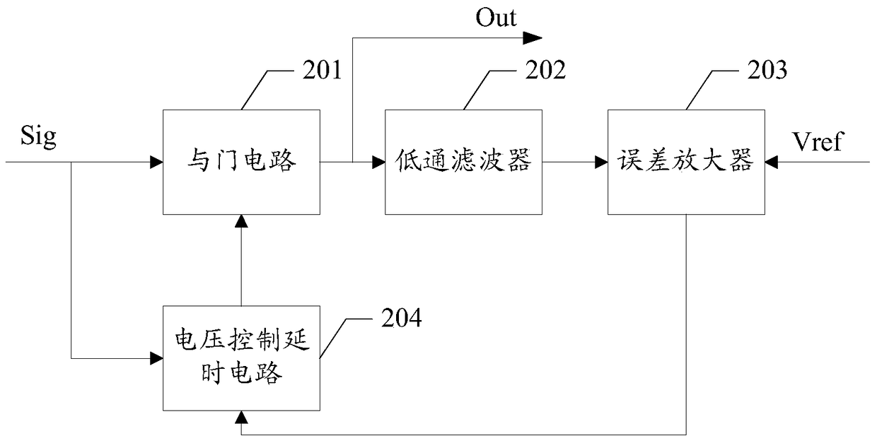
[0004] However, in the above clock duty ratio adjustment method, the low-pass filter is connected to the operational amplifier. Since both the low-pass filter and the operational amplifier have corresponding poles, the above method has the problem of unstable output clock signal.

Method used


Image

  • Clock signal duty ratio adjustment circuit
  • Clock signal duty ratio adjustment circuit
  • Clock signal duty ratio adjustment circuit

Examples


Embodiment Construction

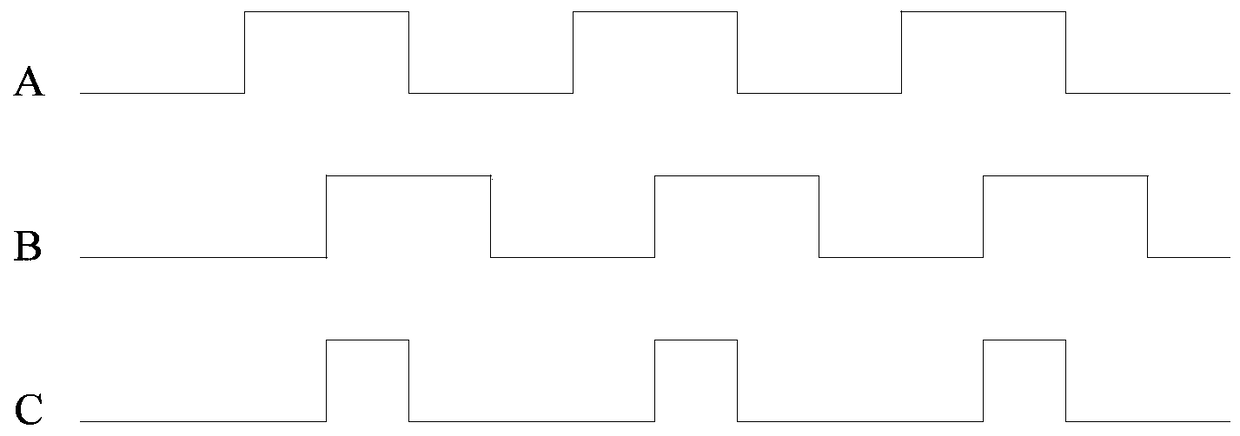
[0024] refer to figure 1 The timing diagram, A represents the waveform of the clock signal with a duty ratio of 50% generated by the clock generation circuit, B represents the waveform of the clock signal with a duty ratio of 50% after the delay circuit, and C represents A and B The waveform after passing through the AND gate circuit can generate a clock signal with a duty ratio of 25%. However, although the above solution is relatively easy to implement, there are large errors because the parameters of the delay circuit itself will change with changes in process, temperature, voltage and other environmental factors.

[0025] In order to overcome the above-mentioned problems, another clock duty ratio adjustment method appears. refer to figure 2 , including: an AND gate circuit 201 , a low-pass filter 202 , an error amplifier 203 and a voltage-controlled delay circuit 204 . The AND gate circuit 201 performs an AND operation on the clock signal Sig with a duty cycle of 50% a...


PUM


Abstract

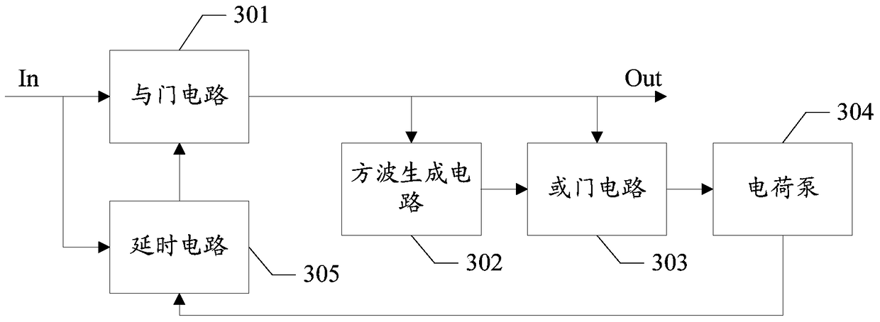
A clock signal duty ratio adjusting circuit comprises a time delay circuit, an AND gate circuit, a square wave generating circuit, an OR gate circuit, and a charge pump. The input end of the charge pump is coupled to the output end of the OR gate circuit, and the output end is coupled to a first input end of the time delay circuit. A second input end of the time delay circuit inputs a clock signal of preset first duty ratio, and the output end is coupled to a second input end of the AND gate circuit. A first input end of the AND gate circuit inputs the clock signal of preset first duty ratio, and the output end is coupled to the clock input end of the square wave generating circuit and a first input end of the OR gate circuit and outputs a duty ratio adjusted clock signal. The output end of the square wave generating circuit is coupled to a second input end of the OR gate circuit, and the square wave generating circuit is suitable for generating a square wave of preset second duty ratio. By using the adjusting circuit, the problem that the output clock signal is unstable during clock signal duty ratio adjustment is avoided effectively.

Description

technical field [0001] The invention relates to the field of clock adjustment, in particular to a clock signal duty ratio adjustment circuit. Background technique [0002] In practical applications, the duty cycle of the clock signal generated by the usual clock generation circuit is 50%. In some special application scenarios, clock signals with other duty ratios are required, for example, the duty ratio of the input clock signal is 25%. [0003] The existing clock duty ratio adjustment generally adopts a method combining a delay circuit and an AND gate circuit. However, although the above solution is relatively easy to implement, there are large errors because the parameters of the delay circuit itself change with changes in process, temperature, voltage and other environmental factors. In order to overcome the above problems, another clock duty ratio adjustment circuit appears, including: AND gate circuit, low-pass filter, error amplifier and voltage control delay circui...

Claims


Application Information

Patent Timeline
Patent Type & Authority Patents(China)
IPC IPC(8): H03K3/017
Inventor 荀本鹏刘飞郭萌萌唐华杨海峰
Owner SEMICON MFG INT (SHANGHAI) CORP
Learn More