U-shaped structure underframe

A technology of concave base frame and base frame, applied in the field of concave structure base frame, can solve the problems of complex manufacturing process of base frame, low transportation efficiency, structural fatigue failure, etc., achieve simple and reliable connection method, avoid structural fatigue failure, The effect of reducing the weight of the car body

Inactive Publication Date: 2016-10-12
CRRC MEISHAN
View PDF8 Cites 5 Cited by
  • Summary
  • Abstract
  • Description
  • Claims
  • Application Information

AI Technical Summary

Problems solved by technology

Due to the limitation of the length and size of the concave bottom part of the existing flat car with concave bottom, the bottom of the vehicle cannot be loaded with containers of specifications above 40 ft, and the transportation efficiency is not high. In addition, the traction beam of the existing flat car with concave bottom adopts a special B-shaped steel beam, and the structure of the traction pillow is overlapped up and down The double-drawing beam and double-bolt beam structure is complicated to assemble. The lower side beam adopts the form of cold-formed B-shaped steel and cold-formed channel steel back cover. The frame manufacturing process is complex and heavy

Method used


Image

  • U-shaped structure underframe
  • U-shaped structure underframe
  • U-shaped structure underframe

Examples


Embodiment Construction

[0024] Below in conjunction with accompanying drawing, the present invention is described in detail.

[0025] In order to make the object, technical solution and advantages of the present invention more clear, the present invention will be further described in detail below in conjunction with the accompanying drawings and embodiments. It should be understood that the specific embodiments described here are only used to explain the present invention, not to limit the present invention.

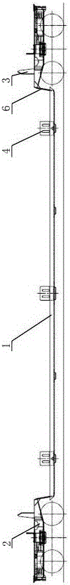
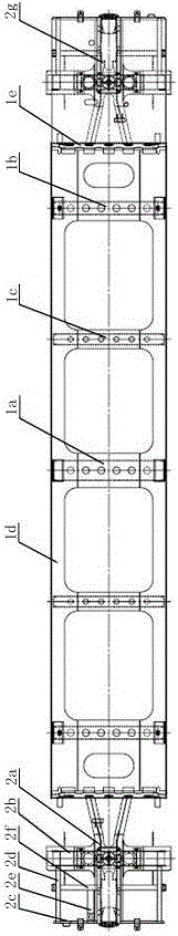
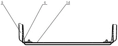
[0026] Such as figure 1 and 2 As shown, a concave structure chassis includes a central concave chassis 1 and end chassis 2 arranged at both ends of the central concave chassis 1. The central concave chassis 1 is composed of a central crossbeam 1a, a crossbeam A1b, The beam composition B1c, the lower side beam 1d and the end vertical plate 1e are assembled and welded, and the end chassis 2 is composed of a traction beam 2a, a corbel 2b, an end beam 2c, an auxiliary side beam 2d, a small beam 2...


PUM


Abstract

The invention discloses a U-shaped structure underframe which comprises a middle U-shaped underframe body and end underframe bodies arranged at the two ends of the middle U-shaped underframe body. The middle U-shaped underframe body is formed by installing and welding a center cross beam assembly, cross beam assemblies A, cross beam assemblies B, a lower side beam and vertical end plates. Each end underframe body is formed by installing and welding a traction beam, a sleeper beam, an end beam, an auxiliary side beam, a small cross beam, a longitudinal beam and a floor. The middle U-shaped underframe body is connected with the corresponding end underframe bodies through the vertical end plates at the two ends. According to the U-shaped structure underframe, the length of the middle U-shaped underframe body is fully utilized, the requirements for loading and container allocating of various containers are met, the line gauge is utilized to the maximum extent, a train bottom bearing face is designed to the allowed minimum value, and the U-shaped structure underframe has great potential economic benefits.

Description

technical field [0001] The invention belongs to the technical field of railway wagons, in particular to a concave structure underframe mainly used for railway double-deck container transport vehicles. Background technique [0002] Railway double-layer container stacking transportation is an important technical means and method of modern logistics and container multimodal transport. With the development of social economy and more and more frequent domestic and foreign trade, how to improve the efficiency of container transportation equipment and effectively Cost reduction has become an important subject of research by those skilled in the art. my country's main type of double-deck container transport dedicated concave bottom flat car, mainly used for loading two 20ft or one 40ft container on the lower layer, and two 20ft or one 40ft-53ft container on the upper layer. Due to the limitation of the length and size of the concave bottom part of the existing flat car with concave...

Claims


Application Information

Patent Timeline
Patent Type & Authority Applications(China)
IPC IPC(8): B61F1/00B61F1/10
CPCB61F1/00B61F1/10
Inventor 谷美娜林结良赵寿鑫刘映安杨清帆陆强李貌徐祖银杨艳萍张光宇程会霞
Owner CRRC MEISHAN
Why Eureka
Try Eureka