Helicopter rotor wing compound motion parallel driving device

A helicopter rotor and compound motion technology, which is applied in the field of helicopters, can solve the problems of low load-bearing tensile capacity of the ball pair, complex rotor motion drive device, and low speed, and achieve the effects of good force bearing, simple structure and improved service life of the ball pair

Active Publication Date: 2016-10-12
YANSHAN UNIV
View PDF13 Cites 18 Cited by
  • Summary
  • Abstract
  • Description
  • Claims
  • Application Information

AI Technical Summary

Problems solved by technology

However, the existing rotor motion drive device is still very complicated
Compared with thrust bearings and tapered roller bearings, the suitable speed of the ball pair is lower, and the bearing capacity of the ball pair is lower

Method used


Image

  • Helicopter rotor wing compound motion parallel driving device
  • Helicopter rotor wing compound motion parallel driving device

Examples


Embodiment Construction

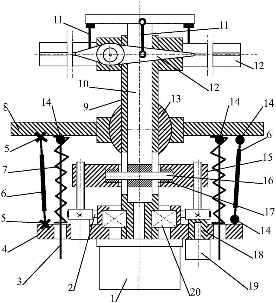
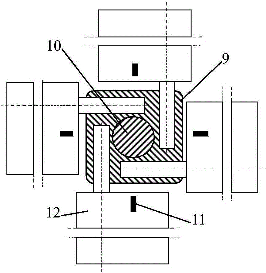
[0016] exist figure 1 and figure 2 In the schematic diagram of the helicopter rotor compound motion parallel driving device shown, the parallel mechanism includes the base, the moving table, the middle SP-type passive restraint branch, the UPU-type driving branch connecting the base and the moving table, and two SPS-type driving branches with the same structure , to realize the axial movement of the main shaft of the rotor and the three-dimensional rotation around the center ball pair of the base; the center of the base 8 is provided with a concave spherical surface hole; Three through holes evenly distributed and three through holes evenly distributed on the large circumference; the middle SP-type passive restraint branch includes a main shaft 9, a large bearing 20 and a ball sleeve 13, and the ball sleeve is provided with an outer spherical surface and a ball center The main shaft with the central through hole is connected with the through-hole cylindrical pair of the ball...


PUM


Abstract

A helicopter rotor wing compound motion parallel driving device comprises a parallel mechanism, a rotor wing swinging mechanism and a spring set. The parallel mechanism comprises a machine base, a movable table, a middle SP type passive confinement branch, a UPU type driving branch and two SPS type driving branches, and the parallel mechanism is used for achieving axial movement and three-dimensional rotation around ball pairs in the center of the machine base of a spindle of a rotor wing. The rotor wing swinging mechanism comprises wing sets, the spindle, an engine, a push rod mechanism, a core rod and connecting rods. Each wing set is rotatably connected with the upper end of the spindle. The engine fixed to the movable table drives the spindle and the wing sets to rotate. The push rod mechanism drives the core rod to move along the spindle, and the core rod rotates along with the spindle. The upper end of the core rod drives the wing sets to swing synchronously relative to the upper end of the spindle through the connecting rod set. The spring set is supported between the machine base and the movable table and used for relieving the acting force of the lift force of the rotor wing to all the driving branches. The helicopter rotor wing compound motion parallel driving device has the advantages that the structure is simple and compact, the stress of the ball pairs is good, the main rotor wing swings and rotates flexibly, and control is easy.

Description

technical field [0001] The invention relates to the field of helicopters, in particular to a driving device for a helicopter rotor. Background technique [0002] Helicopter rotor motion drive device is the key component of helicopter motion. Usually the rotor consists of a hub and several blades. The hub is mounted on the rotor shaft, and the blades, which are shaped like slender wings, are attached to the hub. When the blade rotates, it interacts with the surrounding air to generate a pulling force along the rotor axis. If the direction of the relative airflow or the pitch of each blade is asymmetrical to the rotor axis, a component force perpendicular to the rotor axis is also generated. On a helicopter, the direction of the rotor axis is close to vertical, so the rotor first has the function of a wing, generating upward force. Secondly, it also has a function similar to that of an aircraft propulsion device, generating forward force. It also has a function similar to ...

Claims


Application Information

Patent Timeline
Patent Type & Authority Applications(China)
IPC IPC(8): B64C27/14B64C27/10
CPCB64C27/10B64C27/14
Inventor 路懿路扬何苗
Owner YANSHAN UNIV
Why Eureka
Try Eureka