
Sticky coal blending combustion bi-directional feeding device

A technology of two-way feeding and sticking of coal, applied in the directions of transportation, packaging, loading/unloading, etc., can solve the problems of unstable operation of the generator set, coal blocking, and high frequency of valve use, so as to achieve the function of diverting and blocking, and reduce the occupation. space, and the effect of reducing the probability of material blocking

Active Publication Date: 2016-10-12
河南濮润智能机械工程有限公司
View PDF8 Cites 4 Cited by
  • Summary
  • Abstract
  • Description
  • Claims
  • Application Information

AI Technical Summary

Problems solved by technology

The existing feeding device basically adopts the coal bunker to feed the material. Under the action of gravity, the coal flow is easy to cause stacking pressure and confluence, resulting in dense coal seam. As a result, the phenomena of coal shedding and coal blocking frequently occur during the transportation process, resulting in poor operation of the generator set. Stable, affecting the normal coal output and economical operation of the unit
[0003] At the same time, most of the existing feeding devices use valves (such as gate valves) to control the storage and discharge of materials. The valves are used frequently, wear quickly and are easy to block, which increases the economic cost.

Method used


Image

  • Sticky coal blending combustion bi-directional feeding device
  • Sticky coal blending combustion bi-directional feeding device
  • Sticky coal blending combustion bi-directional feeding device

Examples


Embodiment Construction

[0026] The present invention will be described in detail below in conjunction with the accompanying drawings.

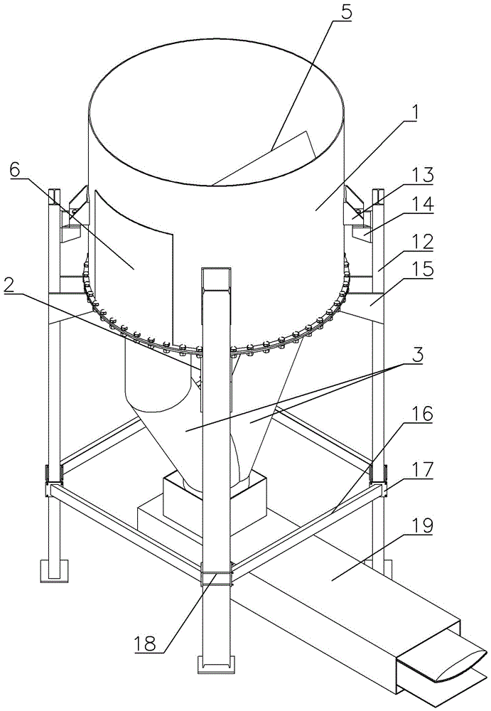
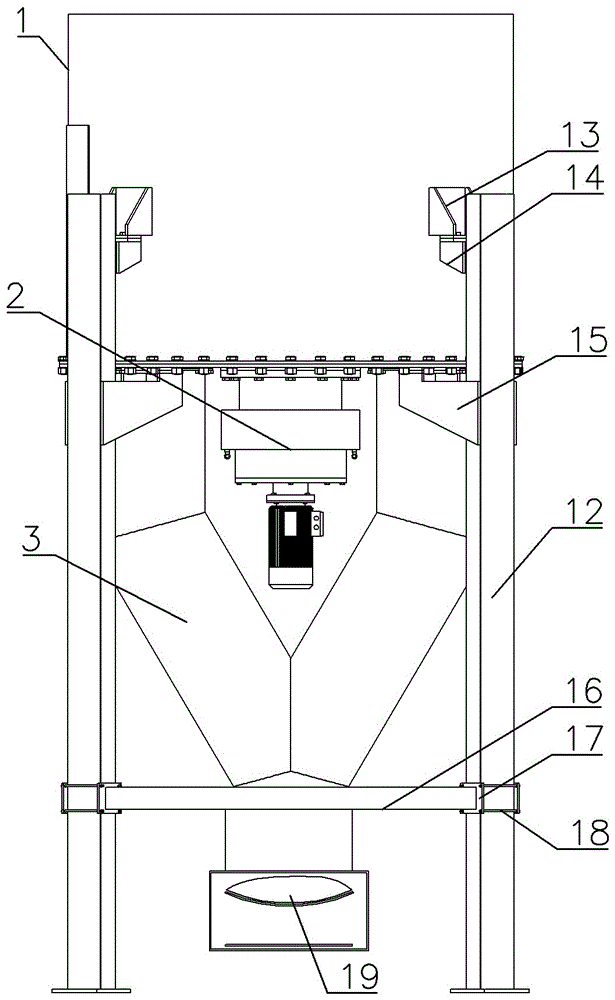
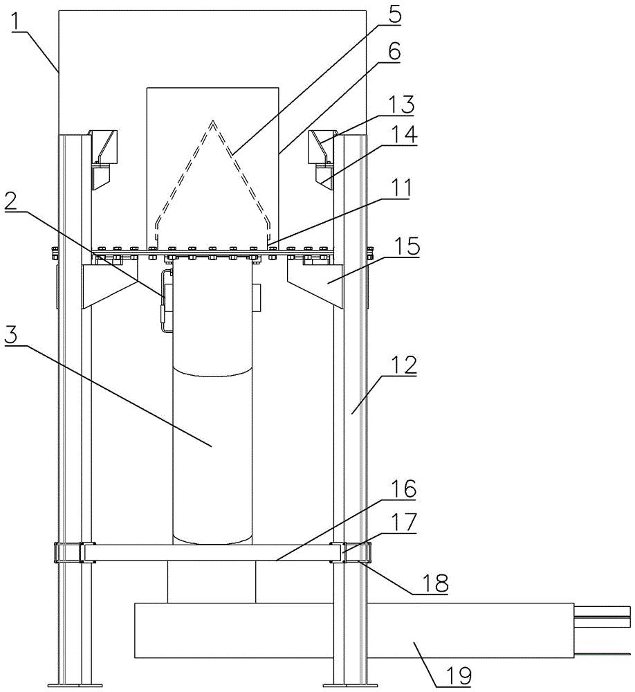
[0027] Two-way feeding device for sticky coal mixed combustion, its structure is as follows Figure 1~4 As shown, it includes a coal bunker 1, a rotary cutting body, a power system 2 and a coal drop pipe 3.

[0028] The coal bunker 1 includes a side wall and a bottom plate made of NM400 wear-resistant material, and the side wall and the bottom plate of the coal bunker 1 are connected by a flange. Two discharge openings 4 are arranged symmetrically along the bottom plate axis of the coal bunker 1, and the lower part of each discharge opening 4 is connected with a coal drop pipe 3, and the coal drop pipe 3 includes a straight pipe section located below the discharge opening 4 and a The inclined pipe section connected below the straight pipe section, the lower ends of the inclined pipe section of the two coal falling pipes 3 are connected, the coal falling pipe 3 can n...


PUM


Abstract

The invention discloses a sticky coal blending combustion bi-directional feeding device and belongs to the field of sticky coal blending combustion feeding devices. The sticky coal blending combustion bi-directional feeding device comprises a coal bunker, two discharging ports are symmetrically formed along the axis of a bottom plate of the coal bunker, the lower portion of each discharge port is connected with a coal dropping pipe, and the bottom ends of the two coal dropping pipes communicate with each other. A splitter plate is arranged above the two discharging ports, and the two ends of the splitter plate are fixed to the side walls of the coal bunker. The coal bunker is internally provided with a rotary cutting body, the rotary cutting body comprises a base body and three cutters symmetrically arranged along the center of the base body, a power system is arranged below the center of the bottom plate of the coal bunker, and the power system is connected to the center of the base body. Materials in the coal bunker are alternately pushed by the rotary cutting body into the coal dropping pipes, the space for original materials is supplemented with materials on the upper portion under the action of gravity, first come first go of the materials is achieved, linking control is matched, a feeding device channel is kept smooth all the time, the materials come while the other materials go, and quantitative blocking preventing is achieved.

Description

technical field [0001] The invention belongs to the field of sticky coal mixed burning feeding device, and in particular relates to a sticky coal mixed burning two-way feeding device. Background technique [0002] Combined with my country's energy strategic plan and the status quo of energy supply, coal used for electricity is mostly added with sticky coal and other raw coal with low calorific value to supply boilers. Due to the physical characteristics of sticky coal that is easy to stick, the raw coal is easy to adhere to the inner wall of the coal bunker during the coal supply operation, and the raw coal is easy to agglomerate itself or with the surrounding raw coal. The existing feeding device basically adopts the coal bunker to feed the material. Under the action of gravity, the coal flow is easy to cause stacking pressure and confluence, resulting in dense coal seam. As a result, the phenomena of coal shedding and coal blocking frequently occur during the transportatio...

Claims


Application Information

Patent Timeline
IPC IPC(8): B65G65/40B65G65/48
CPCB65G65/40B65G65/48
Inventor 赖云河赖道广吕承涛
Owner 河南濮润智能机械工程有限公司
Learn More