A hydraulic pumping unit

A pumping unit and hydraulic technology, which is applied in the field of hydraulic pumping units, can solve the problems of bulky size, poor balance effect of pumping units, troublesome transportation and installation, etc., to ensure firmness and stability, reduce self-weight load, and reduce noise effect

Active Publication Date: 2019-03-12
TIANJIN URANUS HYDRAULIC MACHINERY
View PDF10 Cites 0 Cited by
  • Summary
  • Abstract
  • Description
  • Claims
  • Application Information

AI Technical Summary

Problems solved by technology

This kind of equipment is cumbersome, and it is troublesome to transport and install, especially on offshore oil production platforms, it is not allowed to use large-scale equipment
Moreover, the working principle of the pumping unit is to use a four-bar linkage mechanism to convert rotary motion into linear reciprocating motion. This type of structure will inevitably cause poor balance of the pumping unit during movement. On offshore oil production platforms, this type of pumping The unbalanced nature of machine motion is a serious and fatal problem

Method used


Image

  • A hydraulic pumping unit
  • A hydraulic pumping unit

Examples


Embodiment Construction

[0013] Below in conjunction with embodiment, the present invention is further described, and following embodiment is illustrative, not restrictive, can not limit protection scope of the present invention with following embodiment.

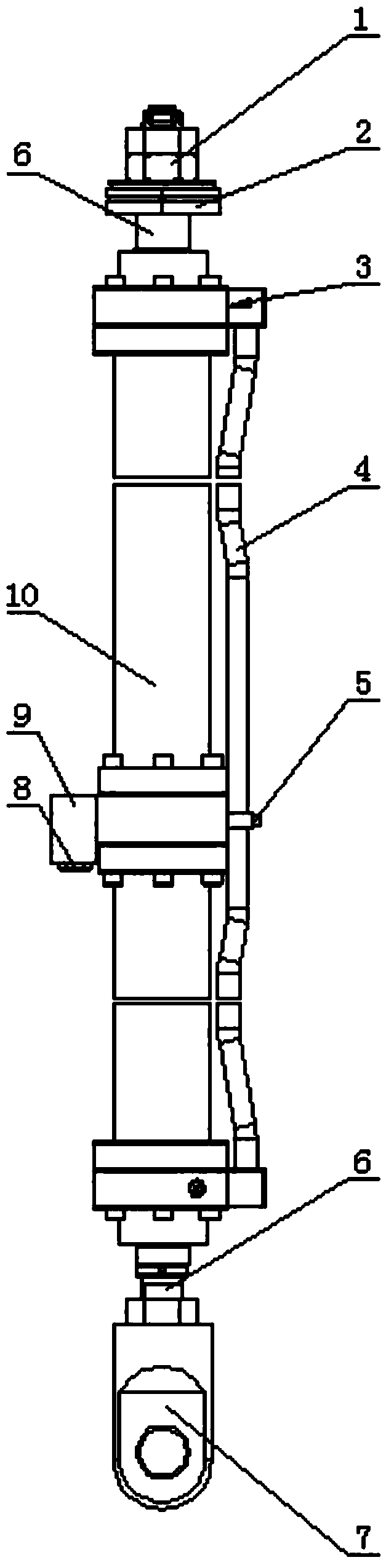
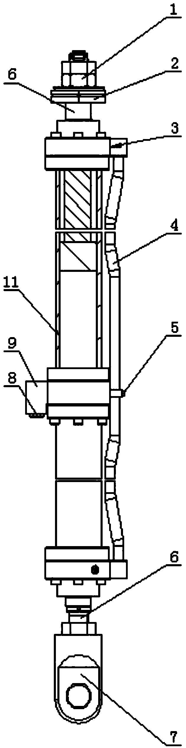
[0014] A hydraulic pumping unit, the innovation of the present invention is that it includes two hydraulic cylinders 10, the rear cavities of the two hydraulic cylinders are relatively fixed and installed, and the insides of the two rear cavities communicate with each other to form a cavity 11, and the two hydraulic cylinders A cylinder oil port 3 is formed in the front cavity of the cylinder, and the oil ports of the two cylinders are communicated through an oil pipe 4, and an oil port 5 is formed in the side wall of the oil pipe, and the two piston rod ends of the two hydraulic cylinders are located at the same vertical In the straight line, reciprocating up and down, the ends of the two piston rods of the hydraulic cylinder are respectively used ...


PUM


Abstract

The invention relates to the field of hydraulic device manufacturing, and in particular to a hydraulic oil pumping unit which comprises two hydraulic cylinders, wherein rear cavities of the two hydraulic cylinders are oppositely arranged and fixedly mounted; interiors of the two rear cavities are mutually communicated to form a cavity; front cavities of the two hydraulic cylinders are communicated through an oil tube; an oil hole is formed inside the side wall of the oil tube; the end parts of two piston rods of the hydraulic cylinders are positioned inside a same vertical straight line and move up and down in a reciprocation manner; the end parts of the two piston rods of the hydraulic cylinders are respectively fixed with a fixing device and the end part of an oil pumping rod; the rear cavities of the two hydraulic cylinders are respectively fixedly connected with two side end parts of a transition block; the transition block and the inner walls of the rear cavities of the two hydraulic cylinders form a cavity for accommodating air; an exhaust hole is formed in the transition block; the exhaust hole is communicated with the external environment.

Description

technical field [0001] The invention relates to the field of hydraulic device manufacturing, in particular to a hydraulic pumping unit. Background technique [0002] The traditional beam pumping unit is directly driven by an ordinary AC asynchronous motor. Its crank belt drives the sucker rod with counterweight and balance weight, and drives the downhole oil well pump to do up-and-down reciprocating motion in a fixed period, so as to send the downhole oil to the surface. This kind of equipment is cumbersome, and transportation and installation are relatively troublesome, especially on offshore oil production platforms, it is not allowed to use large-scale equipment. Moreover, the working principle of the pumping unit is to use a four-bar linkage mechanism to convert rotary motion into linear reciprocating motion. This type of structure will inevitably cause poor balance of the pumping unit during movement. On offshore oil production platforms, this type of pumping However,...

Claims


Application Information

Patent Timeline
Patent Type & Authority Patents(China)
IPC IPC(8): E21B43/00F15B15/14F15B15/20
CPCE21B43/121F15B15/1423
Inventor 齐杨王超光刘兵于安才张建
Owner TIANJIN URANUS HYDRAULIC MACHINERY
Why Eureka
Try Eureka