A turbocharger bearing sleeve and turbocharger

A turbocharger and bearing sleeve technology, applied in the direction of machines/engines, engine components, mechanical equipment, etc., can solve the problems of angular contact ceramic bearings scattered, supercharger damage, rubbing shells, etc., to achieve reliability , the effect of simple structure

Active Publication Date: 2017-12-22
张运波
View PDF5 Cites 0 Cited by
  • Summary
  • Abstract
  • Description
  • Claims
  • Application Information

AI Technical Summary

Problems solved by technology

[0003] In the existing turbocharger, due to the elastic change of the wave spring washer, the axial movement of the turbine rotor shaft and the angular contact bearing is too large, causing the angular contact ceramic bearing to scatter, the supercharger is damaged and the casing is rubbed

Method used


Image

  • A turbocharger bearing sleeve and turbocharger
  • A turbocharger bearing sleeve and turbocharger
  • A turbocharger bearing sleeve and turbocharger

Examples


Embodiment 1

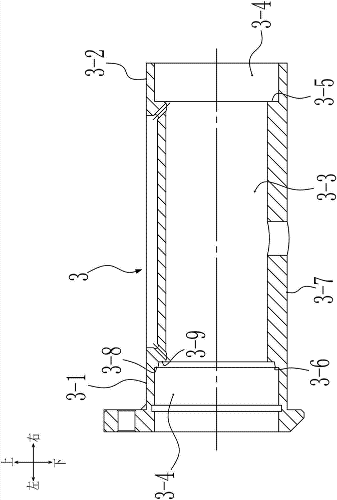
[0023] Such as figure 1 A turbocharger bearing sleeve is shown, which includes a straight sleeve body 3-7, the sleeve body 3-7 has a shaft hole 3-3 passing through along its axis, the sleeve The inner sides of the pressure end 3-1 and the scroll end 3-2 of the body 3-7 are provided with a bearing positioning hole 3-4 coaxial with the shaft hole 3-3, and the diameter of the bearing positioning hole 3-4 is larger than the The diameter of the shaft hole 3-3, the bottom of the bearing positioning hole 3-4 of the pressure end 3-1 is provided with an annular boss 3-6, and the diameter of the annular boss 3-6 is smaller than that of the bearing The diameter of the positioning hole 3-4 is larger than the diameter of the shaft hole 3-3. The shaft hole 3-3, the annular boss 3-6 and the bearing positioning hole 3-4 form a stepped hole. Specifically, on the side of the pressure end 3-1, the first shoulder 3-8 is formed between the outer end surface of the annular boss 3-6 and the inner ...

Embodiment 2

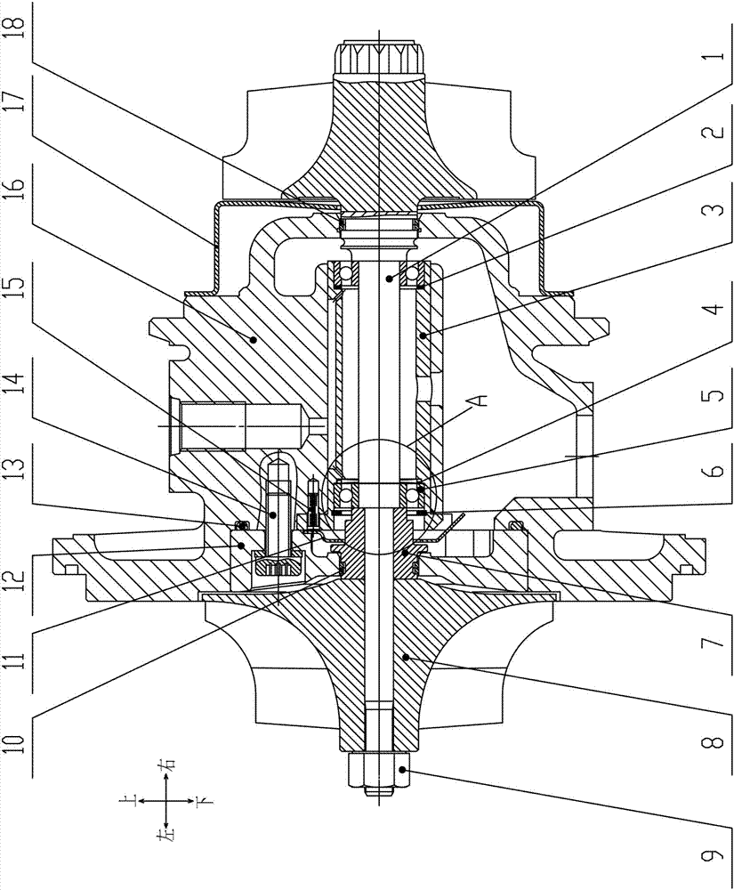
[0026] Such as figure 2 and 3 Shown is a turbocharger, which includes a bearing body 16, a turbine rotor shaft 1, a pressure end seal ring 10, an oil baffle plate 11, an O-ring 13, an oil seal screw 14, a spring pin 15, and a heat shield 17. Turbine end seal ring 18, oil seal cover 12, shaft seal sleeve 7, compressor impeller 8 and impeller lock nut 9, and also include bearing sleeve 3 and two angular contact bearings 5 ​​as described in Embodiment 1; The oil seal cover 12 fixes and connects the shaft bearing sleeve 3 into the bearing body 16, the shaft seal sleeve 7 and the compressor impeller 8 are sequentially arranged on the turbine rotor shaft 1, and the turbine The impeller lock nut 9 at the left end of the rotor shaft 1 is fastened.

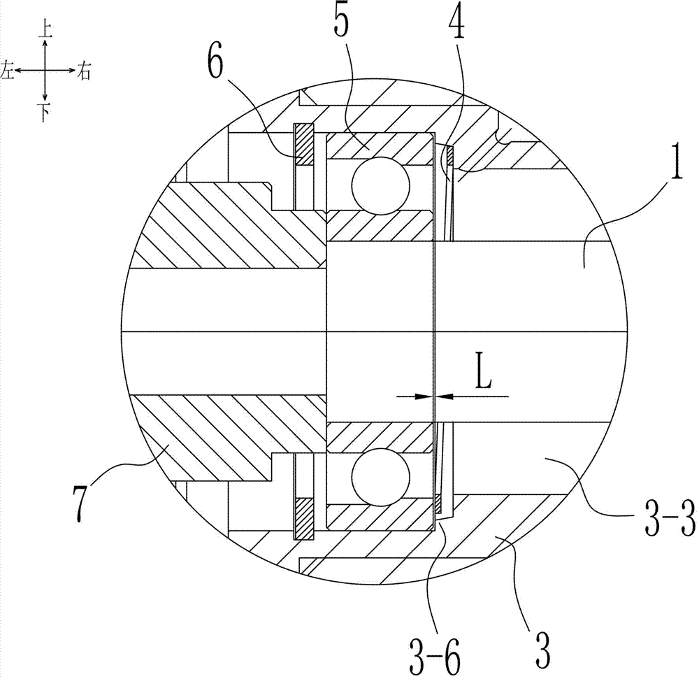
[0027] The two angular contact bearings 5 ​​are set on the turbine rotor shaft 1, the bearing sleeve 3 is set on the turbine rotor shaft 1, and the two angular contact bearings 5 ​​are arranged on the bearing sleeve 3 In the bearing po...


PUM


Abstract

The invention relates to a turbocharger bearing sleeve and a turbocharger comprising the bearing sleeve. The bearing sleeve comprises a straight-sleeve-type sleeve body; the sleeve body is provided with an axial hole which is through in the axis direction; the inner sides of the pressing end and the vortex end of the sleeve body are each provided with a bearing positioning hole for containing an angular contact bearing; the diameter of each bearing positioning hole is larger than that of the axial hole; an annular boss is arranged at the bottom of the bearing positioning hole of the pressing end; and the diameter of the annular boss is smaller than that of the corresponding bearing positioning hole and larger than that of the axial hole. A wavy spring gasket is arranged in a hole of the annular boss of the pressing end and makes contact with the outer circle end faces of the angular contact bearings; the wavy spring gasket provides pre-tightening force for the angular contact bearings; and the annular boss limits the movement range of the angular contact bearings.

Description

technical field [0001] The patent of the present invention relates to the technical field of turbochargers, in particular to a design of the structural arrangement of angular contact ceramic ball bearings, which is suitable for the application of exhaust gas turbochargers of various gasoline and diesel engines. Background technique [0002] With the use of angular contact ceramic ball bearings on exhaust gas turbochargers, the axial precision can be adjusted under the condition of ensuring the preload, which has changed the fact that turbocharger manufacturers cannot produce by themselves due to high manufacturing precision and must rely on bearings. The manufacturer manufactures the integral bearing and supplies it to the supercharger manufacturer. This separate structural arrangement fulfills the same technical requirements. [0003] In the existing turbocharger, due to the elastic change of the wave spring washer, the axial movement of the turbine rotor shaft and the ang...

Claims


Application Information

Patent Timeline
Patent Type & Authority Patents(China)
IPC IPC(8): F01D25/16
CPCF01D25/16
Inventor 张运波
Owner 张运波
Why Eureka
Try Eureka