
Combustion apparatus

A combustion device, burner technology, applied in the direction of burners, combustion chambers, burners, etc.

Active Publication Date: 2016-10-12
NORITZ CORP
View PDF5 Cites 9 Cited by
  • Summary
  • Abstract
  • Description
  • Claims
  • Application Information

AI Technical Summary

Problems solved by technology

However, in such a case, the same problem as above will arise

Method used


Image

  • Combustion apparatus
  • Combustion apparatus
  • Combustion apparatus

Examples


Embodiment Construction

[0033] Hereinafter, preferred embodiments of the present invention will be specifically described with reference to the drawings.

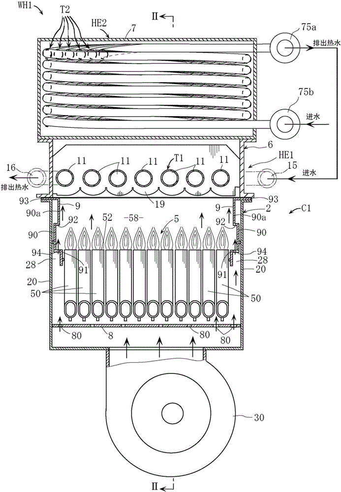
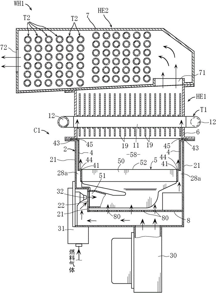
[0034] figure 1 and figure 2 The combustion device C1 shown is used as a component of a water heater (hot water supply device) WH1 capable of heating hot water. exist figure 1 Among them, the combustion device C1 includes: a burner 5, which generates combustion gas; a burner housing 2, which accommodates the burner 5; a fan 30, which is used to supply combustion air to the burner housing 2; and a pair of partitions hot plate9. In addition, if figure 2 As shown, the combustion device C1 also includes a pair of additional heat shields 4 . The hot water supply device WH1 includes a primary heat exchanger HE1 and a secondary heat exchanger HE2 for heating hot water by sequentially recovering sensible heat and latent heat from the combustion gas generated by the burner 5 .

[0035] The basic configurations of the primary heat exchanger HE1 an...


PUM


Abstract

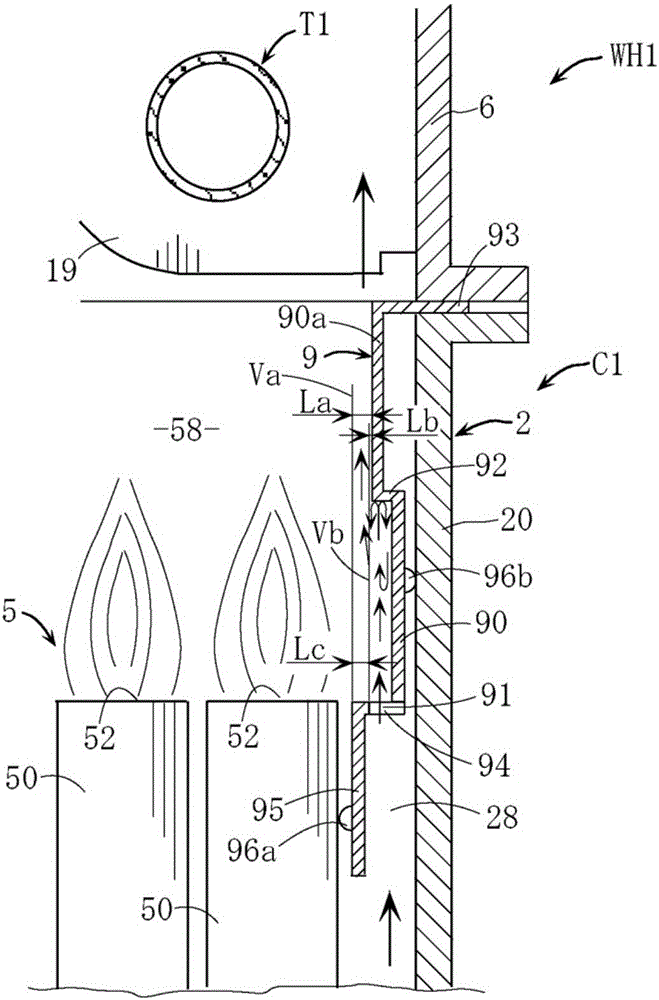
A combustion apparatus includes a burner and a heat shield plate. The heat shield plate includes a main plate portion located on a lateral side of a flame formation region above the burner to erect, a stepped portion protruding from a lower end of the main plate portion toward the burner and set at approximately the same height as that of a flame hole surface of the burner, and air passage holes provided in the stepped portion. The main plate portion is provided with a facing wall portion which protrudes from a middle part of the main plate portion in a vertical height direction thereof toward the flame formation region and faces the air passage holes so as to be subjected to a collision with air travelling upward from the air passage holes.

Description

technical field [0001] The present invention relates to a combustion device applied to a hot water supply device and the like. Background technique [0002] Specific examples of the combustion device include those described in Patent Document 1 and Patent Document 2. [0003] In the combustion apparatuses described in these documents, a heat insulating plate is disposed inside a side wall portion of a burner housing for accommodating the burner. A substantially horizontal step portion is formed at a position near the lower portion of the heat shield, and an air passage port is provided in the step portion. A part of the air sent into the burner housing from the fan attached to the bottom of the burner housing flows upward through the air passage port and along the inner surface of the heat shield plate. Thereby, it is possible to obtain the effect that the heat shield plate is cooled, and the air flow blocks the contact between the flame of the burner, the combustion gas, ...

Claims


Application Information

Patent Timeline
Patent Type & Authority Applications(China)
IPC IPC(8): F24H1/16F24H9/18
CPCF23M9/02F24H1/165F24H9/1836F23C7/02F23D14/045F23D2203/007F23D2214/00F23L5/02F24H9/0026F23D1/00F24H9/148
Inventor 马越亮辅
Owner NORITZ CORP
Learn More